Synopsys and Ansys power the future of innovation—connecting silicon to systems.
-
-
학생용 무료 소프트웨어에 액세스하기
차세대 엔지니어에게 힘을 실어주는 Ansys
학생들은 세계적 수준의 시뮬레이션 소프트웨어를 무료로 이용할 수 있습니다.
-
지금 바로 Ansys에 연결하십시오!
미래를 설계하기
시뮬레이션이 다음 혁신을 어떻게 지원할 수 있는지 알아보려면 Ansys와 연결하십시오.
무료 트라이얼
제품 및 서비스
학습하기
회사 정보
Back
제품 및 서비스
ANSYS BLOG
April 12, 2023
What is Highly Accelerated Life Testing (HALT)?
Assessing the robustness of an electronic product is integral to successful design and performance. Highly accelerated life testing, or HALT, is an important testing tool for this purpose, and its effectiveness can be maximized through careful planning prior to setup and detailed execution.
What is HALT?
HALT is the process of applying increased stressors to an electronic device to force failures and uncover design and construction weaknesses. The stressors applied are typically well beyond the expected field environments to quickly discover failures. This enables engineers to optimize designs, repair or replace failed components, and lower product development costs.
HALT Procedures
Setting clear expectations and directives for conducting HALT is a multistep process that starts with bringing the design engineers together to:
- Develop a test plan based on reliability physics, including understanding potential failure modes and mechanisms and clearly defining the objectives.
- Determine the expected environments, including applicable stresses such as temperature, vibration, and shock.
- Decide how many devices under test (DUTs) are available for HALT testing. Generally, one to five samples are used.
- Select the functional tests to be run during testing, such as what the device should be doing, which circuits should be active, and what codes and sensors should be gathering data.
- Identify which parameters need to be monitored based upon the desired functional tests and application.
- Define what constitutes a failure. This could include failing a functional test (monitored either continuously or periodically during test), observing physical damage, failing to remain operational, etc.
- Consider using reliability simulation software to simulate the vibration and thermal loads so a model can be created that may reach HALT limits.
In conjunction with developing the foundational outline, two key areas must be addressed.
1. Applicable Stresses
Select the appropriate stresses and stress levels for HALT testing:
- Vibration
- High temperature
- Low temperature
- Voltage/frequency margining
- Power cycling
- Combined stresses (i.e., temperature and vibration)
Choosing the appropriate stresses is dependent upon the application and the environment in which the device operates. Suspect parts or areas of concern within the device can also help drive what stress levels to apply in test.
2. Step Stress Approach
For each intended stress, clearly delineate:
- The starting stress point.
- The amount by which to increment the intended stress in each step.
- The duration of each step.
- The device or equipment limit for that stress.
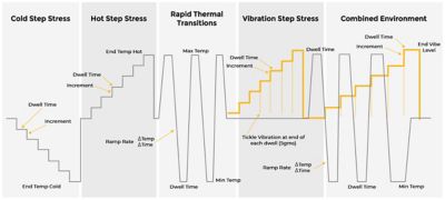
Step stresses applied in HALT.
Typically, the operating and destructive limits of the device are not known prior to testing. HALT testing can be used to determine this through the step-stress approach. If failure occurs during monitoring or functional testing, the stress is subsequently reduced until the DUT recovers from the failure. This failure is known as the operating limit. When the stress is increased above the operating limit and the DUT can no longer recover without a repair, the destruct limit has been reached.
Setting Up a HALT
For accurate results, particular attention must be paid to the HALT configuration:
- Design a vibration fixture to ensure vibrational energy is being transmitted into the product.
- Design air ducting to ensure thermal energy is being transmitted into the product. This can include modification of the DUT to allow unimpeded airflow inside the device.
- Tune the chamber for the sample being tested.
- Determine locations for thermocouples and accelerometers to monitor temperature and acceleration, respectively.
- Set up all functional test equipment and cabling.

Conducting a HALT
HALT is comprehensive and encompasses several testing phases, each with specific parameters to follow.
Thermal Step Stress
Thermal step-stress testing applies incremental temperature stress levels throughout the product life cycle in order to identify product failure modes.
- Connect the power and functional test equipment to the DUTs. Additional product-specific stresses may or may not be applied depending on the application.
- Begin with cold step stress, followed by hot step stress.
- Initially use 10 °C increments, decreasing to 5 °C increments as limits are approached.
- Set the dwell time minimum at 10 minutes plus the time needed to run a functional test. Timing should commence once the temperature being monitored on the DUT has reached its set point.
- Continue the test until operating and destruct limits are determined, or maximum stress as dictated by the test plan.
Thermal Shock Cycling
Thermal shock cycling is conducted between the DUT’s operating limits determined above. This exposes the DUT to fast thermal transitions, sometimes 60 ˚C per minute or as fast as the testing equipment/chamber allows.
- Connect the power and functional test equipment to the DUTs. Additional product-specific stresses may or may not be applied depending on the application.
- Keep the temperature range between 10 °C below the upper operating limit and 10 ˚C above the lower operating limit determined during step-stress testing.
- If the sample cannot withstand maximum thermal transitions, decrease the transition rate by 10 °C per minute until the allowable rate is found.
- Continue hot and cold thermal transitions with 10-minute dwells at each extreme for five total cycles.
Vibration Step Stress
Vibration step stress testing applies incremental vibrational stress levels in order to identify product failure modes.
- Connect the power and functional test equipment to the DUTs. Additional product-specific stresses may or may not be applied (power cycling, line voltage/frequency margining, etc.), depending on the application.
- Determine the G-level root mean square (Grms) increments, typically ranging from 3-5 Grms on product.
- Set the dwell time minimum at 10 minutes plus the time needed to run a functional test.
- At 30 Grms and above, perform “tickle” vibration between setpoint vibrations. The tickle vibration is performed at 5 Grms while performing the functional check.
- Continue the test until the operating and destruct limits are determined, or maximum stress as dictated by the test plan.
Combine Vibration and Thermal Shock Testing
Merge testing results and methodologies to further test products.
- Connect the power and functional test equipment to the DUTs. Additional product-specific stresses may or may not be applied (power cycling, line voltage/frequency margining, etc.), depending on the application.
- Use the vibration destruct limit and divide by 5 to determine the step increase at each of the five thermal cycles for this test.
- Use the thermal shock cycle limits and ramp rate for the five thermal cycles.
- At 30 Grms and above, perform a “tickle” vibration between setpoint vibrations (to manifest failure modes not evident under high vibration amplitudes or static conditions). The tickle vibration is performed at 5 Grms while performing the functional check.
Post-HALT Monitoring and Failure Analysis
Once HALT is completed, the design engineers’ focus becomes determining the root causes of all failures and corrective action. This can include identifying the failure site and failure mechanism for each failure mode. Afterwards, a verification HALT needs to be implemented to evaluate if testing adjustments fixed the problems.
Ansys Sherlock can shortcut this process by creating simulations based on testing models before any physical sample modification or the verification HALT takes place, saving time and money. In addition, our Reliability Engineering Services team can perform Accelerated Life Testing once the weak points in the design have been resolved and final testing required.
Contact us today to discuss how we can help streamline your HALT process and accurately confirm results.