-
-
학생용 무료 소프트웨어에 액세스하기
차세대 엔지니어에게 힘을 실어주는 Ansys
학생들은 세계적 수준의 시뮬레이션 소프트웨어를 무료로 이용할 수 있습니다.
-
지금 바로 Ansys에 연결하십시오!
미래를 설계하기
시뮬레이션이 다음 혁신을 어떻게 지원할 수 있는지 알아보려면 Ansys와 연결하십시오.
국가
무료 트라이얼
제품 및 서비스
학습하기
회사 정보
Back
제품 및 서비스
ANSYS BLOG
July 25, 2023
What’s New for Digital Mission Engineering in Ansys 2023 R2
With the Ansys 2023 R2 release, digital mission engineering products continue to unlock enhanced multidomain systems simulation capabilities by placing an expanded focus on streamlining modeling and simulation workflows. Ranging from advancement of on-orbit simulation, support for cislunar spacecraft missions, and expanded trajectory modeling for flight procedures, new capabilities make it even easier to connect detailed multidomain mission simulations with high-fidelity systems models and support the expanding needs of design and test engineers.
Additionally, the new release further strengthens the connectivity of modeling and simulation artifacts between Ansys Orbit Determination Tool Kit (ODTK) and Ansys Systems Tool Kit (STK) to provide users with enhanced flight dynamics capabilities. It is critical to design and test these complex missions under realistic simulated conditions and find solutions to ensure the safety of flight of the systems once they transition to operation and sustainment.
CR3BP System Configuration Design Tool Added
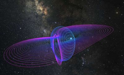
As interest continues to build around cislunar and other multibody spacecraft missions, trajectory designers are particularly interested in planning and analyzing missions in the vicinity of the libration (or Lagrange) points. These points exist in systems involving the motion of a spacecraft relative to two gravitating bodies whose influence on the spacecraft is roughly equivalent. Spacecraft motion in the vicinity of these points can follow strategically useful paths, including particular orbital solutions relative to the points. These motions often provide suitable geometry for imaging, mapping, communications relays, navigation support, and other situations in which a consistent relative position might be ideal. More importantly, they follow the fundamental motions associated with spacecraft in this regime that must be leveraged to carry out a given mission.
A lower-fidelity model suitable for initial trajectory design and analysis is the Circular Restricted Three-Body Problem (CR3BP). To effectively use this model within STK, the software environment must be appropriately configured to account for its unique considerations. With this latest release, STK’s Astrogator capability now offers a design tool to construct the necessary framework to use the CR3BP in STK. The CR3BP configuration design tool is made available within Astrogator’s component browser to create and define other components to support this framework, serving as a customizable, encapsulated mechanism to configure STK. Providing a simplified workflow/mechanism to set up STK for use with the CR3BP dynamical model saves users both time and effort.

Circular restricted three-body problem (CR3BP) simulated in Ansys STK.
Improved On-orbit Safety of Flight Analysis
A necessary step during trajectory planning and analysis is ensuring safety of flight. When the trajectory is constructed relative to another object in space, safety of flight often centers on avoiding collisions between two objects. While there are various elements in this analysis, one component involves verifying that missed maneuvers do not result in a collision. This can be accomplished through a "what-if" assessment to determine cases in which flight safety constraints would be violated. Upon eliminating such trajectories, the results may be deemed passively safe, subject to the given constraints.
The STK Passive Safety tool is intended to work in concert with rendezvous and proximity operations (RPO) planning and analysis. The tool leverages Astrogator simulations and performs a comprehensive assessment against user-specified keep-out volumes. For each maneuver in an RPO itinerary, the resulting motion if any given maneuver is missed is evaluated relative to the keep-out criteria to determine if it is passively safe. Those involved in relative motion trajectory activities will benefit from the added efficiency represented by this tool. They must go through passive safety analyses at various stages of design, analysis, and operations, and this tool represents an out-of-the-box option to simplify their workflows. Users who are involved in any spacecraft trajectory design activities with tools such as Astrogator that entail relative motion will find this very effective at establishing safety of flight considerations-associated maneuver modeling.

Rendezvous and proximity operations simulated in Ansys STK.
Advanced Model-based Systems Engineering Behavioral Modeling
The Behavior Execution Engine (BEE) now has added enhanced support for configuring projects to work with STK Engine. While customers have always had the ability to quickly and easily configure their projects to leverage STK Desktop, this enhancement extends to STK Engine. Customers can configure their projects with STK Engine to significantly reduce runtime when visualizations are not required.
Customers can connect their simulation with STK Desktop during development to confirm correct and complete implementation, then switch to an STK Engine configuration to improve simulation runtime. Customers running large trade studies will benefit from being able to run simulations in the no graphics mode of STK Engine. This is also an advantage for customers who have simulations that do not require visualization during runtime.
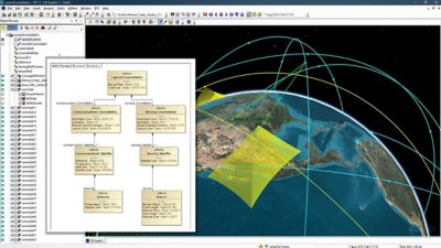
In the past, BEE simulations could only be run from within No Magic (Cameo) and required a running instance of SysML to execute the simulation. BEE has added a standalone execution capability so customers can run a BEE simulation by direct reference to a properly constructed .mdzip file.

SysML integrations with Ansys STK.
Improved Formation Flight
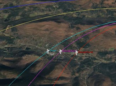
To drastically reduce computation time for flight in formations, the Aviator tool introduces a new formation flier procedure that follows the rendezvous basic maneuver and propagates existing formations through straight and basic turning flight. This new procedure reduces analysis time for customers carrying out long-range formation flight, providing a 90% reduction in calculation time over the rendezvous procedure. Customers who need to keep aircraft in formation flight for long distances for uses such as long-range refueling analysis will benefit from this new procedure.

A formation flight modeled in Ansys STK.
Statistics Tool Improvements
Test and Evaluation Tool Kit (TETK) has added box and whisker plots as well as histograms to the existing graphing options provided to users for exploring statistical analysis of their post-flight data. The Box and Whisker Plot option helps users understand and measure the spread of data points and provides a 1.5 interquartile range (IQR) box with median, mean, variance, and IQR displayed for one or several data elements. In addition, the Histogram Plot option provides the display of mean, median, mode, and variance of user-selected data elements. This latest release continues to provide engineers and analysts with the data reduction tools necessary to fully understand and categorize the performance of their systems under test. With these new features, customers have improved analysis ability for post-test data and can consolidate more of their work within STK.
Enhanced Workflows for Managing Multiple Tracks
TETK has added a number of features to improve track analysis for customers importing vehicle trajectory data that may originate from sensor systems such as radar, laser ranging, or optical tracking systems. Customers can now filter points associated with a specific track ID and advance through them to better understand and visualize data associated with that individual tracked object. Additional usability enhancements include unit switching, font adjustment options, and time filtering to control how the track data is represented. These improvements allow users to quickly understand the relationship between their track data and truth position to better evaluate their test data and validate system performance during testing events.
Customers analyzing sensor data will enjoy a quicker and more intuitive way to focus on the most relevant data and customize the way it is represented to suit their needs. This is especially useful for customers who need to analyze radar and command and control system performance.
GNSS Antenna Phase Center
With this latest release of ODTK, users can now specify ANTEX formatted files available from the International GNSS Service (IGS), which contain Global Navigation Satellite System (GNSS) antenna information for satellites belonging to navigation constellations such as GPS. ODTK will now utilize this information — which includes mean phase center locations and variations in the antenna’s perceived position as a function of the transmission frequency and GNSS receiver direction — to improve the fidelity of GNSS measurement modeling. For satellite owners and operators who rely on tracking data from onboard GNSS receivers, this is another step in achieving improved GNSS-based orbit determination solutions.
This provides an enhanced level of accuracy and fidelity that might otherwise not be included or represented with general assumptions or baseline values, which can contribute to inaccuracy in final orbital solutions. This will benefit any customer processing pseudorange carrier phase measurements as part of their spacecraft tracking data.
Be on the lookout over the next few months for digital mission engineering feature specific blogs and webinars to learn more.