-
-
Accédez au logiciel étudiant gratuit
Ansys donne les moyens à la prochaine génération d'ingénieurs
Les étudiants ont accès gratuitement à un logiciel de simulation de classe mondiale.
-
Connectez-vous avec Ansys maintenant !
Concevez votre avenir
Connectez-vous à Ansys pour découvrir comment la simulation peut alimenter votre prochaine percée.
Pays et régions
Espace client
Support
Communautés partenaires
Contacter le service commercial
Pour les États-Unis et le Canada
S'inscrire
Essais gratuits
Produits & Services
Apprendre
À propos d'Ansys
Back
Produits & Services
Back
Apprendre
Ansys donne les moyens à la prochaine génération d'ingénieurs
Les étudiants ont accès gratuitement à un logiciel de simulation de classe mondiale.
Back
À propos d'Ansys
Concevez votre avenir
Connectez-vous à Ansys pour découvrir comment la simulation peut alimenter votre prochaine percée.
Espace client
Support
Communautés partenaires
Contacter le service commercial
Pour les États-Unis et le Canada
S'inscrire
Essais gratuits
ANSYS BLOG
December 6, 2023
Breaking the Cycle of Brake Dust Emissions
When you think of automobile emissions, most likely an image of gas fumes exiting the tailpipe comes to mind. But automobiles emit other potentially polluting particles that you probably haven’t considered, coming from brake wear, tire wear, and road abrasion. In fact, only 15% of emissions come from the exhaust, with the remaining 85% coming from these other sources. Of these, small metal particles emitted from the brake disc have the best chance of capture by filtration. The European Union (EU) is considering legislation to control all emissions from vehicles, including brake disc particles.
Engineers at MANN+HUMMEL, located in Ludwigsburg, Germany, with additional engineering support from their India offices, are using Ansys Fluent to simulate the flow of metal particles as they leave the brakes. The goal is to design a passive filter (i.e., no moving parts) that fits onto the brake calipers to capture these particles before they exit into the surroundings.
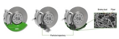
Filter concept for MANN+HUMMEL brake dust particle filter (BPDF) showing the filter unit in green, attached to the brake pads. Emitted brake dust is entrapped in a filter grid made of metal fiber.
The decision to use Ansys software was an easy one for the engineering team.
“We had the great advantage of a lot of engineers who had experience with Ansys Fluent,” says Christoph Schulz, Manager Simulation Filter Elements at MANN+HUMMEL. “So, Ansys was the first choice for us when we started on this project.”
The Challenge of Modeling Brake Particle Emissions
Though the brake disc/pad system appears to be relatively simple, it’s more difficult to model than you might think.
“The physics of brake disc particle creation and flow is not fully understood,” Schulz says. “You could research and write several Ph.D. dissertations about this topic before you could really completely understand it.”
Any simulation of this system with the addition of a brake dust particle filter (BDPF) must consider (among other variables):
- The entire flow field inside the BDPF, which is generated by the rotation of the inner ventilated brake disc.
- The material of the brake pad, brake disc, and metallic filter.
- The separation efficiency of the filter for metal particle sizes ranging from 0.1-10 µm.
- The probability of a metal particle impacting the filter medium so it can be captured.
- Quasi-static flow rates ranging from 10-130 km/h.
- Thermal effects as the BDPF heats up during braking.
Expanding on some of these points, Schulz explains that the materials of the brake disc (mainly cast iron) and the brake pad (made of metals including iron, copper, steel, and graphite bonded together) differ depending on the manufacturer of these components, so the amount of friction that develops between them during braking varies. This friction causes metal particles from the disc to form in different sizes and quantities. So, the size and number of particles are dependent on brake manufacturers, temperature, and the force applied by the hydraulic braking system.
Temperature also determines whether the metal particles are released into the air that travels through the brake or if they stick to the disc at first and release later. When they release, they enter the inner ventilation system of the disc, which consists of holes through which cooling air flows. This airflow can vary significantly depending on the driving speed and wind conditions.
In designing a BDPF, the engineers also have to be careful that the filtration system does not add to the airflow problem. The metal mesh that serves as the filtration medium also slows down airflow, especially when the filter has been in use for a while and the mesh becomes clogged with entrapped particles. Reduced airflow can lead to undesired overheating.
“All these variables add to the complexity of designing a brake particle filtration device,” Schulz says, “and complexity can lead to uncertainty in design.”
Reducing Uncertainty Through Simulation
In lieu of funding several Ph.D. candidates to research and write dissertations to solve these challenges, Dr. Florian Keller, Director of Engineering Air Filter Elements and Simulation at MANN+HUMMEL, led a research effort to better understand and track the flow of particles through a brake system equipped with a BDPF. As he wrote in the resulting journal paper “Development of a Modeling Approach to Numerically Predict Filtration Efficiencies,” published by SAE International.
“While computational fluid dynamics (CFD) simulations for inner-ventilated brakes have become state of the art, a holistic model from particle generation and emission to particle dynamics in the vicinity of the brake is not yet available.”
The paper describes his team’s efforts to develop such a holistic model using Fluent to simulate filtration for 10 different filter designs and four floating caliper brake systems.
The BDPFs used in the simulations consist of a housing filled with a pleated metal fiber filter grid placed on both axial surfaces and on the radial surface of the housing. The pleats increase the surface area of the filtration medium. The housing attaches to the brake caliper. When the brake disc rotates, it causes air to flow through the inner ventilation and into the BDPF. This air contains metal particles from the brakes, which may become entrapped in the filter mesh. The goal of the simulations was to determine the fraction of metal particles leaving the brake that were captured by the filter.
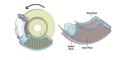
Pleated filter structure of the brake dust particle filter.
According to the paper, Keller and his team set up the simulations using a moving reference frame (MRF) approach, in which the Navier-Stokes fluid flow equations in Fluent are transformed from the stationary frame to a moving frame. This is accomplished by taking into account the relative velocity of particles in the moving reference frame, the velocity in the inertial frame, the angular velocity, and the position vector from the origin of the moving frame. Using this approach, the acceleration of the air includes the Coriolis and centrifugal forces, which drive the air flow in the inner ventilation region.
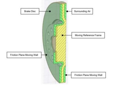
Brake disc showing the moving reference frame simulation concept.
The team used discrete phase modeling (DPM) to inject, track, and analyze particle behavior and ultimately compute the filtration efficiency of the BDPF. Discrete particles of sizes 0.1 µm, 0.5 µm, 1 µm, 2 µm, 3 µm, 5 µm, 7 µm, and 10 µm having a density of 2,650 kg/m3 were injected into the simulation domain at four injection points in the vicinity of the brake pad.
The number of integration steps for particle trajectory tracking was set to 70,000 to reduce incomplete tracks. The simulated particle tracks revealed by Fluent show that the particles first move radially towards the filter medium and then flow alongside the filter element circumferentially. When metal particles reached the surface of the filter medium, they were considered trapped, while particles leaving the outlet of the domain were considered to have escaped.
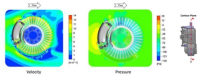
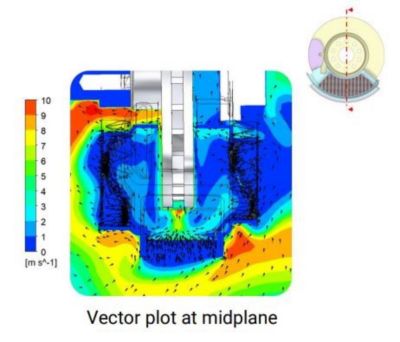
Velocity and pressure contour simulation results for flow in a brake system containing a brake dust particle filter (BDPF)
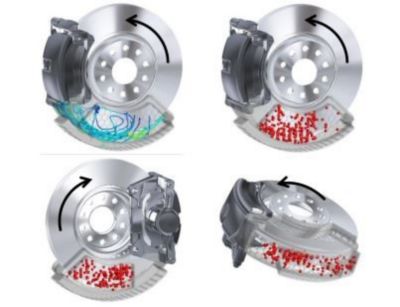
Particle tracks and impingement locations from one simulation run.
From these simulations, Keller’s team was able to track the flow of metal dust particles that came from the brake pad and the disc, predict the probability of impact with the filter medium, determine the particle size distribution, and calculate the overall filtration efficiency of the 10 BDPF designs. The probability that a dust particle would impact the filtration medium was as high as 80% for one of the designs.
MANN+HUMMEL engineers developed a physical braking testing bench to compare simulation results with experimental ones. Keller and his team concluded that, using Fluent simulation, filtration results can be predicted with up to 10% accuracy compared to physical tests for the WLTC Class 3 cycle of automobiles, which includes vehicles with the highest power-to-mass ratio, representative of vehicles driven in Europe and Japan.
Even with such a close agreement between simulated and experimental results, simulations provided much more detail.
“What you don't get easily from a test bench is an impression of the flow field and of the particle movement itself,” says Schulz. “So, this is something where you really have a big advantage using simulation. If you look at this brake system, there are a lot of small gaps where particles could escape and avoid the filter element. It's much easier to see these gaps in a simulation than in a real test bench. Fluent is a big benefit in revealing the details of flow and particle movement.”
Learn more about how Ansys Fluent can help you.