-
-
학생용 무료 소프트웨어에 액세스하기
차세대 엔지니어에게 힘을 실어주는 Ansys
학생들은 세계적 수준의 시뮬레이션 소프트웨어를 무료로 이용할 수 있습니다.
-
지금 바로 Ansys에 연결하십시오!
미래를 설계하기
시뮬레이션이 다음 혁신을 어떻게 지원할 수 있는지 알아보려면 Ansys와 연결하십시오.
국가
무료 트라이얼
제품 및 서비스
학습하기
회사 정보
Back
제품 및 서비스
ANSYS BLOG
August 2, 2021
When Will Aircraft Be Certified by Analysis?
The consensus among the major aircraft OEMs is that the time is now ripe for new simulation technologies to gain more acceptance from airworthiness agencies. Simulation tools and methods have improved so much in the last two decades that it can no longer be left to individual efforts by each OEM to justify, for each new aircraft, the use of these tools.
Certification by Analysis (CbA) has become an organized, community-led effort by the OEMs to reach a consensus that can then be submitted to the authorities for approval. It will by no means lead to the OEMs using common tools and methodologies, but rather define clear standards under which their proprietary approaches can be determined to meet the certification requirements.
Nowhere in the aircraft certification procedure is there more of a need to modernize certification as in the in-flight icing area. Many of the tools that are currently accepted date from the 1980s. The argument against more advanced tools has traditionally been the lack of validation, often demanding that validation be on the exact situation that is being simulated.
By defining generic acceptance standards for simulation tools, CbA may finally remove this roadblock and ease the way for more realistic simulation methods. This new simulation-driven era will necessarily impose structural changes within the airworthiness organizations, calling for experts with deeper knowledge of simulation methods. That process has begun in earnest.
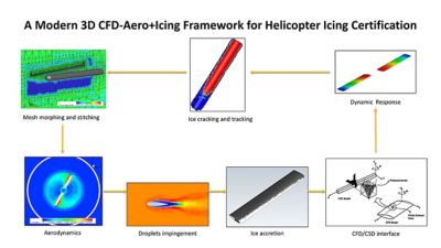
A helicopter flow demonstrates current simulation capabilities. Flows with rotating and stationary components, in hover and in forward flight, are some of the most complex icing simulations.
Attend the Online International Course on Icing Simulation
The 19th International Icing Course, which almost 100 organizations have attended in the past, will be held online October 12-15, 2021.
It will present the latest combined computational fluid dynamics (CFD) and experimental fluid dynamics EFD) simulation (yes, dry and icing testing are considered “simulation”) tools for in-flight icing. Instructors of the course have been advocating the use of realistic 3D approaches for individual components, as well as the aircraft as a system. An aircraft should not be analyzed airfoil section-by-airfoil section. Why?
An aircraft is an integration of systems each affected by the other.
The flow over the wings is affected by the engine location and pylon shape and vice versa, yet they are certified separately.
Ice on the cockpit windows is strongly affected by the flow over the nose of the aircraft and the ice-protection system (IPS) melting the ice from these windows may refreeze and form a ridge on top of the fuselage.
The smallest components need as much attention as the largest ones. Angle of attack (AoA) vanes and Pitot tubes are strongly affected by the deviation of air and droplets enrichment by the fuselage. They are “the mouse that can kill, and has killed, the elephant.”
The 2D manufactured ice shapes tested on aircraft during certification bear little resemblance to the 3D ice that will actually form in flight: How could this be accepted?
Any conclusions on flow separation over 2D iced airfoils sections are meaningless, as the overall 3D flow bears no resemblance to the sectional 2D ones. An airplane wing has sweep, twist, break and sometimes vortex generators, all meant to prevent a local stall.
In other words, the world is three dimensional and one would be remiss, for the sake of quick certification, not to use tools that could solve problems that may sooner or later show up during operation.
However, the introduction by an OEM of CFD results, particularly 3D ones, is sometimes seen as a possible reason for delay in certification. However, not every CFD calculation is meant for presentation to authorities; a majority are performed internally to ensure aircraft safety and compatibility of the ice assessment to the aerodynamic one.
Address 3D Simulation Concerns
Objections to the use of 3D simulations are many, including:
3D calculations take time, requiring computer-aided design (CAD), meshing, long run times and careful interpretation, which is way more than the quick-and-dirty answers given by 2D methods.
It could be argued that CFD calculations are highly dependent on meshes, users and turbulence models.
Some smaller manufacturers may not have a CFD expert on staff.
The International Icing Course will clearly resolve these difficulties one-by-one by introducing two technologies guaranteed to lessen, if not eliminate, any arguments against CFD accuracy.
The first is automatic mesh optimization (OptiGrid), in which the mesh is automatically adapted to the evolving solution at hand. It can be shown that, starting from any initial mesh, OptiGrid will lead to the same final optimal mesh, thus blunting the any mesh density and user influence.
Secondly, reduced order models (ROMs) have become important tools in the arsenal of the icing community. Defining the critical points for an aircraft, whether related to the aerodynamics or the thermodynamics, is usually a tedious process of sorting out a multitude of scenarios that can be encountered at all phases of flight and within the entire rules appendices. Carrying out a number (say 50) of initial 3D (complete aircraft) snapshot calculations – at different Mach numbers, AoAs, altitudes, droplet sizes and liquid water contents – each take from one to two days to execute sequential calculations of flow, impingement, ice accretion and performance degradation. But because they are independent calculations, they can be carried out simultaneously to form a response surface that can be quickly interrogated for any desired change in the five parameters.
How quickly then can the interrogation of a 20-million-mesh-point response surface be done for a new Mach number, AoA, altitude, droplet size and liquid water content set in order to yield all CFD information at 20 million points, including flow, impingement, ice accretion and performance degradation? The answer is astonishing: 1/100th of a second on a PC!
ROM technology opens an era in which 3D calculations are faster than 2D ones and offers the possibility of a pre-calculated in-flight icing CFD desk simulator for companies that do not have a CFD expert on staff.
The world of in-flight icing certification is quickly changing.
Attend the online course from the comfort of your office and with no travel expenses, to see for yourself, exchange ideas with colleagues from all over the world and find out that you are not alone in a quest for new icing simulation technologies.