Synopsys and Ansys power the future of innovation—connecting silicon to systems.
-
-
학생용 무료 소프트웨어에 액세스하기
차세대 엔지니어에게 힘을 실어주는 Ansys
학생들은 세계적 수준의 시뮬레이션 소프트웨어를 무료로 이용할 수 있습니다.
-
지금 바로 Ansys에 연결하십시오!
미래를 설계하기
시뮬레이션이 다음 혁신을 어떻게 지원할 수 있는지 알아보려면 Ansys와 연결하십시오.
무료 트라이얼
제품 및 서비스
학습하기
회사 정보
Back
제품 및 서비스
ANSYS BLOG
January 4, 2019
How to Mesh Watertight CFD Geometry in the New Fluent Task-based Workflow
I admit that I am a computational fluid dynamics (CFD) meshing wizard. I know shortcuts, tricks and application program interfaces (API) from memory. But even this expert is sold on the simplicity of Ansys Fluent’s task-based workflow for watertight geometries.
If you start with a relatively simple model, getting through the task-based workflow is straightforward. You are presented with several steps, like:
- CAD import.
- Surface mesh.
- Describe geometry.
- Capping.
- Flow-volume extraction.
- Volume meshing.
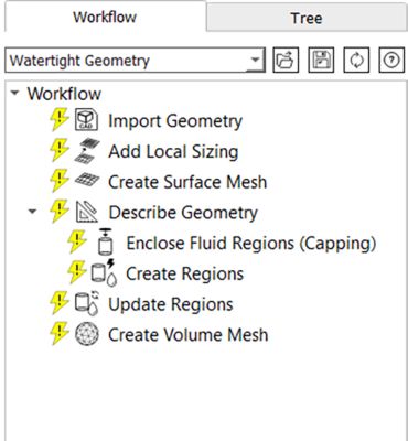
The watertight workflow tree
Now, click on “Switch-to-Solution,” to bring the mesh into a familiar Fluent interface.
But, what if you are looking to simulate a more complicated model — like air cooling an electrical motor? Let’s see some tips and tricks in the watertight geometry workflow to get this complex model pre-processed in no time.
Moving the Flow Volume from Ansys SpaceClaim into Ansys Fluent
If you are creating an internal flow volume, then the capping tools in Ansys Fluent makes extraction easy.
For external flow simulations, like the air flow cooling a motor, we need to create an outer flow boundary in Ansys SpaceClaim.
To do this, draw a cube around the motor and then use the Share Topology function.
Share Topology combines all overlapping faces between two solids into one face. It also resolves the intersection between the cube and any part of the motor.
The flow volume will be extracted as part of the Surface Mesh operation in Fluent. The volume will take the shape of the void between the boundaries of the cube and the motor.
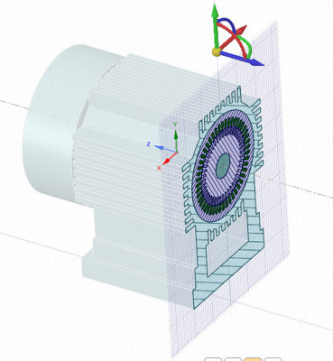
Share Topology defines a flow region without Boolean operations.
Why You Should Name Your Model’s Entities in SpaceClaim
While working on your geometry in SpaceClaim, there are a few other tips and tricks that might make your life easier down the road.
First, include the string “fluid” in the name of the cube around the motor geometry. That will automatically identify it as a fluid region within the watertight geometry workflow.
In fact, make it a habit to add descriptive strings to the names of other entities, like
- Inlets.
- Outlets.
- Symmetry planes.
If you include these strings in the entity name, Fluent will know to define these entities as inlets, outlets, symmetry planes and more.
You are now set to import the motor model into Fluent.
The Benefits of Using Native Fluent Files
Every time you import the CAD model into the Fluent task-based workflow, the software creates a native version of that file (.pmdb).
The next time you need to read in the same model, try reading in the PMDB file. It will be much faster to read the pmdb geometry than the original CAD geometry.
Another advantage with the PMDB file is that it is operating system-independent. This means you can now move your workflow into a Linux environment.
Advanced Options to Speed Up Surface Meshing of CFD Geometry
Assuming you followed the steps in SpaceClaim correctly, there are some surface mesh options you can toggle that will make things mesh faster.
For example, if you used the strings — like “inlet” or “fluid” — when naming entities, you don’t need to use zone separation to determine regions within your surface mesh.
Another option that can be turned off is “Check Self-Intersection.” This operation checks if your model has any overlapping faces. This operation is no longer needed thanks to the Share Topology function.
You are now ready to execute the surface mesh operation.
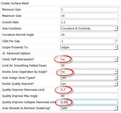
Advanced options to speed up meshing.
Verifying CFD Geometry for Ansys Fluent
During the surface mesh, Fluent will define boundary types to zones and region types to volumes. These definitions are based on the names you created in SpaceClaim.
For example, a boundary named “gas-inlet” will be assigned as a “velocity-inlet” boundary type.
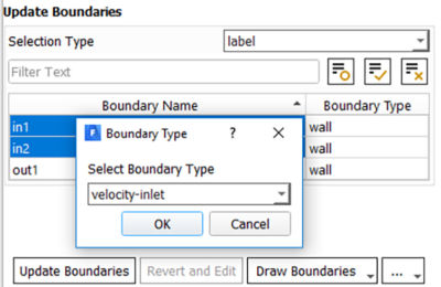
Remember to click “Update” after changing the name or type of a zone.
As a best practice, verify that the boundary and region types were assigned properly before volume meshing.
You can change a boundary or region’s name and type as needed. If you select multiple names and right-click, you can change multiple boundaries or regions into the same type.
Just remember to click “Update” once you are done verifying all the boundary types.
You are now ready to start volume meshing your model.
Volume Meshing Geometry for Fluent
When the volume meshing starts, Fluent will make a fine mesh at the boundary layers. However, maintaining a fine mesh throughout the bulk would be computationally expensive. You can use Mosaic meshing technology to automatically link fine and coarse meshes together.
Frist, you can choose to add boundary layers in the “Create Volume Mesh” panel. These will only be added on fluid region walls. Then, you can access the full suite of conformal volume meshing methods:
- Tetrahedral.
- Hexcore.
- Polyhedral.
- Poly-hexcore.
If you wish to use the latest Mosaic meshing technology, select “Poly-hexcore.”
At this point, the standard watertight geometry workflow is complete, and you are ready to mesh your model. However, you can insert additional tasks into the task-based workflow if they are needed.
For example, you may wish to further refine the volume mesh. Now you have the ability to tweak some standard variables that control the mesh quality.
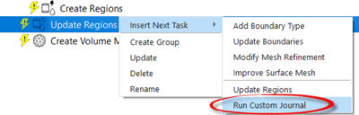
Running custom tasks in the workflow
You can also expand the standard watertight geometry workflow by creating custom journals. These customized tasks can perform advanced Fluent operations that are tailored to your organization. You might want to contact Ansys support to get the user commands needed to set up a custom journal.
Sharing, Saving and Editing the Meshing Watertight Workflows
Some of the biggest benefits of the watertight geometry workflow are that you can save it, return to it and edit it at any point.
So, if you need to make a change early in the task-based workflow, you can — even if you are in the final stages of meshing the geometry.
Once you are satisfied with the workflow, you can save it and share it with your team. This allows you to use the task-based workflow for similar models and should give your team a head start on meshing the next design iteration of your motor.
The watertight geometry workflow can also be built into a script that runs the mesh through the Fluent solver. To create this script, use the “Start Journal” function. Fluent will now record the script as you run through the workflow.
The new watertight geometry workflow has been a significant timesaver. Creating a mesh that is ready for CFD analysis now takes minutes when it used to take hours.
One significant benefit is that you can easily change a variable at any point throughout the workflow — even if you’re returning to it a week later.
To learn more, take the Ansys Fluent Meshing with Watertight Geometry Workflow training.