-
-
Accédez au logiciel étudiant gratuit
Ansys donne les moyens à la prochaine génération d'ingénieurs
Les étudiants ont accès gratuitement à un logiciel de simulation de classe mondiale.
-
Connectez-vous avec Ansys maintenant !
Concevez votre avenir
Connectez-vous à Ansys pour découvrir comment la simulation peut alimenter votre prochaine percée.
Espace client
Support
Communautés partenaires
Contacter le service commercial
Pour les États-Unis et le Canada
S'inscrire
Essais gratuits
Produits & Services
Apprendre
À propos d'Ansys
Back
Produits & Services
Back
Apprendre
Ansys donne les moyens à la prochaine génération d'ingénieurs
Les étudiants ont accès gratuitement à un logiciel de simulation de classe mondiale.
Back
À propos d'Ansys
Concevez votre avenir
Connectez-vous à Ansys pour découvrir comment la simulation peut alimenter votre prochaine percée.
Espace client
Support
Communautés partenaires
Contacter le service commercial
Pour les États-Unis et le Canada
S'inscrire
Essais gratuits
ANSYS BLOG
August 11, 2023
Leveling Up Additive Manufacturing with Layered Tetrahedral Meshing
Companies are on the lookout for innovations that can boost efficiency, both to support sustainability initiatives and improve profit margins. This call for efficiency has led to a digital transformation across the manufacturing industry. Production processes are becoming more innovative by combining digital technologies like simulation with leading-edge additive manufacturing (AM) applications. AM processes add materials layer by layer, and there are digital modeling methods being used today that can accurately capture the complex shape of these AM components, along with the layer-based manufacturing representation of them.
Laser powder bed fusion (LPBF) is an AM process that has shifted from rapid prototyping to end-use functional parts. LPBF presents huge potential in various industries for improving materials efficiency, reducing life cycle impacts, and enabling greater engineering functionality compared to conventional manufacturing methods. As AM systems have become more advanced, AM simulation technologies have been driven to progress at a faster rate. The demand for AM serial production adds further challenges to simulation technologies, requiring a reduction of part post-processing and consideration of the different stages of the AM process chain.
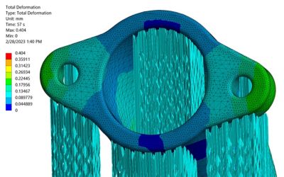
A hexahedral mesh is based on a six-face cubical structure, while tetrahedral mesh is structured from a four-face triangular structure. This simulation shows total deformation of a manifold intake using layered tetrahedral mesh.
One of the key aspects that Ansys has focused on to address geometry and physics complexity is layered tetrahedral mesh (LTM). Both Cartesian meshing — which subdivides additive components into hexahedral elements — and LTM mimic the layer-by-layer build strategy used in AM, but compared to using the Cartesian coordinate system, LTM can capture part complexity more precisely. This meshing technology is natively supported by select structural simulation tools from Ansys and can be used for many applications.
Optimizing Additive Manufacturing: Cleaner Mesh, Products, and Sustainability
Simulation and AM present several opportunities to support sustainability. Software requires minimal natural resources to produce, and the use of simulation and AM can reduce the waste associated with physical prototyping. Further, simulation can be used to enhance AM with topology optimization algorithms that use mathematical techniques. These help engineers optimize product design and remove unnecessary material to save costs and decrease energy consumption. Simulation-powered additive manufacturing can also increase the success rate of first-attempt printing results, which leads to additional savings in cost, energy, and material.
With predictive insight from simulation, designers can make necessary changes earlier in development instead of facing late-stage design failures. For AM, a primary example of this is simulation’s ability to minimize residual stress-induced deformations of a printed part. At the same time, the reduction of unnecessary material leads to the creation of lighter, more efficient structures. In finite element modeling (FEM), these structures are represented as mesh. Lattice structures are commonly used in AM to reduce the mass of an object. In relation, lattice optimization is the substitution of solid material by struts to decrease weight. Historically, finer mesh results in greater accuracy, as it can better capture geometry complexity.
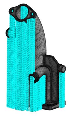
A manifold with support structures highlighted in blue

Heat exchanger model courtesy of Ansys, nTopology, Synopsis, EOS, NSI, and Stress Engineering Services, Inc.
Alleviating a “Mesh” of Challenges
As mentioned above, AM simulation and 3D printing commonly use a uniform hexahedral or voxel mesh method also known as Cartesian mesh. As a layer-based meshing method, this would seem like the best mesh choice for AM, which also uses a layer-based method. However, there are limitations to using a hexahedral mesh in capturing curvature, fine features, and distinct features in close proximity to other features, such as what you might see in an optimized heat exchanger. In addition, mesh geometries can become challenging for a non-expert.
Alternatively, tetrahedral mesh follows the contours of the component itself rather than the line of cubic elements, which is stair-stepped and not smooth. This enables tetrahedral mesh to capture all of the features that hexahedral mesh misses and, subsequently, simplifies the geometry. LTM in particular lends additional benefits to AM processes, including speed, memory, accuracy, and fidelity, by accurately capturing the full complexity of the component with far fewer elements than other mesh methods.
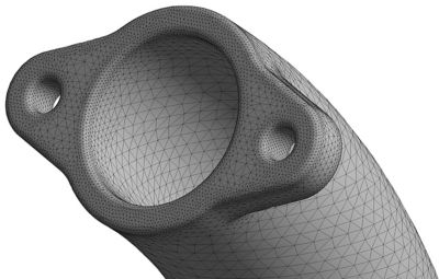
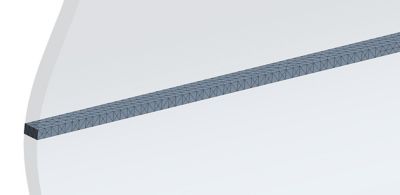
Close-up 3D image of a manifold intake using layered tetrahedral mesh
Discover the Top Benefits of LTM
- Enables high-fidelity results in a quick, neat, and accurate manner.
- Reduces errors and provides accurate mesh representation, making it a preferred choice for complex geometries and thin or fine features.
- Supports sustainability efforts by reducing wasted material, energy, and cost.
- Offers an easy-to-use implementation that democratizes simulation for all users.
Still, meshing can introduce a set of challenges involving geometric inaccuracies. For a non-simulation expert or inexperienced engineer, correcting geometric errors can be time-consuming and, in some cases, unsuccessful. While voxel meshing does reduce the complexity of mesh, LTM simplifies the process even further. In simple terms, hexahedral mesh is based on a six-face cubical structure, while tetrahedral mesh is structured from a four-face triangular structure.
In LPBF technology, it is common to see parts with fine features that, at times, can be measured in microns. To achieve accuracy in finite element analysis (FEA), it is generally recommended that thin features have at least a few elements through the thickness of any section. To satisfy this recommendation, a large number of Cartesian elements is often required, which tends to create longer simulation times and uses more memory. For geometries that include fine details — such as topology-optimized parts — LTM makes it easier to mesh the geometry of a part without increasing the model size or computational time. This helps engineers represent the fine-featured geometry details that AM parts are known for, including narrow channels and thin walls.
In a macroscale additive simulation, layer height defines the number of powder layers embedded in an element. For this reason, layer height is the main input parameter in Ansys’ LTM workflow. Due to its easy-to-use implementation, this type of mesh can bring a lot of value to non-FEA experts. In addition, other mesh sizing options can be used to control the curvatures and mesh, fitting in more demanding geometries.
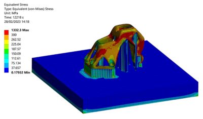
Residual stress result after building an aerospace bracket
Hot Topics: Preventing Printing Defects
There are several pieces of equipment engaged during AM processes. In LPBF, a recoater is the mechanism that sets down layers of fine powder. Of course, there must also be a heat source, which for LPBF is a laser. While heat sources are necessary and enable AM processes, they also create a cluster of thermal-related concerns. Recoater collision, overheating, warpage, and shrinking are defects that are common in LPBF processes and can be caused by high thermal gradients and stresses produced during the build process that may not appear until cooling or post-printing. These defects can lead to poor-quality parts, higher costs, delays in production, and even product failure. Because these defects can occur during printing but appear afterward, it is most ideal to detect and correct these potential blunders before printing the components.
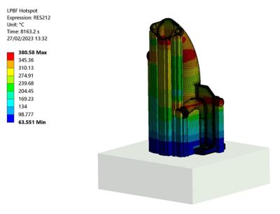
An Ansys Mechanical simulation shows overheated zones of a manifold during laser powder bed fusion (LPBF), a common additive manufacturing (AM) process.
To avoid thermal-related printing errors, LTM is preferred as it not only mimics the printing process, but also helps correlate predicted defects within a given height selection or powder layer. As compared to Cartesian, tetrahedral elements are allowed to be smaller and with local refinement within a layer. Also, for those parts that contain inclined surfaces, tetrahedral elements tend to better capture stresses and strain on the part’s surface.
During FEA, nonlinear effects can originate from various reasons, including the material law used or the contact between parts or large displacements. When it comes to geometries like thin walls, buckling is an undesired nonlinear instability that can lead to build failure. For this type of large deformation analysis, LTM quadratic elements (10 nodes) can lead to a better estimation of the bending behavior of a component. It is important to effectively capture all component features in the mesh representation because nonlinear effects can be caused by any aspect of a geometry. It is hard to know in advance whether a hole or column in a part will lead to imperfections with perturbation load or eigenfrequency.
Another popular AM process is material deposition-based AM. During this process, material flows through a nozzle, is heated, and is then deposited layer by layer. For the same reasons listed above, LTM presents value to this process in its ability to prevent thermal-induced errors. In material deposition-based AM, components are sensitive to warping, overheating, and other thermal issues such as a delamination failure, in which the material fractures or cracks. Printing time is also usually increased due to a broader printing area. However, similar to its aid during LPBF, LTM enables engineers and designers to capture all geometric features in the mesh representation while predicting potential defects.
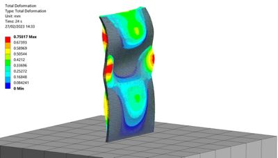
Simulated results in Ansys Mechanical illustrate the total deformation in a curved fin during laser powder bed fusion (LPBF).
In layered tetrahedral mesh (LTM), the displacements calculated in layered mesh (shown here) are mapped onto a target geometry with a faceted mesh.
Setting Things Straight with Simulation, Layer by Layer
Predicting the right deformation is a very important step to correct the distortion of a component. During distortion compensation, the distortion of a component is inverted with a negative value using a given scale factor. An iterative process is also typically used because parts can respond non-linearly. While running the distortion compensation, the displacements calculated in the layered mesh are mapped onto a target geometry with a faceted mesh. While the mapping algorithm is independent of the layered mesh used, LTM is ideal for capturing all component features and does not miss regions that could lead to mapping errors.
As AM becomes more established as a serial production technology, serial numbers and company logos are seen more frequently on components. While these numbers and logos are mostly added later for product branding and quality control, they would not necessarily have an impact on the stress and distortion generated during the build process. However, for thin regions of the components where stress concentration could happen around the labels, LTM could be used to capture defects surrounding these areas.
LTM represents the best meshing option in end-to-end simulation workflows in which AM residual stresses are mapped in connection with a new analysis system for part qualification. For this type of workflow — and to avoid transferring data between dissimilar meshes, i.e., from Cartesian to tetrahedral elements — LTM can be applied to mesh the component for different steps of the product development chain. LTM is also an effective method in which to consider powder representation because the contact between the part and its components can be easily assigned. It also aids in predicting regions of the part that will exceed a maximum elongation, i.e., where only a very fine Cartesian mesh would typically be used. Similarly, LTM is preferred for simulating heat treatment and hot isostatic pressing processes because thermal and pressure conditions can be directly applied to the element faces. In this way, LTM prevents numerical errors and extrapolations that may occur using Cartesian elements.
With its ability to produce high-fidelity results in a quick, neat, and accurate manner, LTM is a preferable choice when working with complex geometries. In the same manner, LTM works well for thin or fine features with its ability to reduce errors and provide an accurate mesh representation while also supporting sustainability by reducing wasted material, energy, and cost. As digital transformation continues to impact the manufacturing industry and more companies explore AM, LTM offers an easy-to-use implementation that democratizes simulation for all users — from beginner to advanced.
Learn more about Ansys additive manufacturing simulation solutions.