Synopsys and Ansys power the future of innovation—connecting silicon to systems.
-
-
Kostenlose Software für Studierende
Ansys unterstützt die nächste Generation von Ingenieur*innen
Studenten erhalten kostenlosen Zugang zu erstklassiger Simulationssoftware.
-
Verbinden Sie sich jetzt mit Ansys!
Gestalten Sie Ihre Zukunft
Stellen Sie eine Verbindung mit Ansys her, um zu erfahren, wie Simulation Ihren nächsten Durchbruch vorantreiben kann.
Kostenlose Demoversionen
Produkte & Dienstleistungen
Lernportal
Über das Unternehmen
Back
Produkte & Dienstleistungen
Back
Lernportal
Ansys unterstützt die nächste Generation von Ingenieur*innen
Studenten erhalten kostenlosen Zugang zu erstklassiger Simulationssoftware.
Back
Über das Unternehmen
Gestalten Sie Ihre Zukunft
Stellen Sie eine Verbindung mit Ansys her, um zu erfahren, wie Simulation Ihren nächsten Durchbruch vorantreiben kann.
Kostenlose Demoversionen
The distribution and orientation of fibers in a composite material has a great impact on its mechanical or thermal properties, and therefore contributes significantly to the performance of a component. Accurate fiber analysis is pivotal to validate designs but is challenging when fibers are densely packed and have diameters on the micron scale within a relatively large part. Simulation can aid this process by predicting the flow patterns during injection molding or casting, and hence the likely fiber orientation. However, these approaches are imperfect and cannot account for part-to-part variations. For thoroughly engineered components, the process and manufactured part must still be validated.
The fiber orientation analysis tools in Ansys Simpleware software enables you to extract orientation information from micro-CT images of the manufactured part which can then be used in a range of ways to understand the real-world performance and lifespan of a component.
Benefits of Simpleware Fiber Orientation Analysis
- Run fast fiber orientation analyses direct from image data, no segmentation required
- Characterize your fibers to understand density and orientation
- Visualize vectors and plot charts to understand and share information with colleagues
- Export detailed orientation information to improve material property representation in your finite element simulation
Example: Fiber Reinforced Plastic Part
Let’s look at an example using a motor mounting bracket made from fiber reinforced plastic (FRP). This lightweight composite material is formed when chopped fiber strands are embedded in a polymer leading to a material with high compressive and tensile strength. This material is used in a vast range of applications including:
- Aerospace components: brackets, wing structures, and flaps
- Automotive: bumpers, brackets, and pedal
- Sports equipment: snowboards, bicycles, and paddles
- And many more
FRP offers increased strength, elasticity, and heat resistance, as well as reduced weight compared to traditional metal components.
A micro-CT scan is used to inspect the fibers in an FRP bracket. There is a maximum size the component that can be scanned for a specified resolution. Therefore, it is usual to take scans of several different sections of the component. These can either be combined to form a highly detailed micro-CT scan of the entire component, or they can be distinct regions of interest (ROI) within the part.
A micro-CT scan showing the fibers in high detail for the whole part will allow for the best fiber density and orientation calculation. However, the size of the part, time, and physical hardware resources may not allow this. Therefore, scans of distinct ROI are a viable alternative solution. These ROI can be selected from regions of likely high stress concentrations by running an initial structural analysis using homogenized material properties based on fiber orientation information from a single region. Once the distinct ROI are scanned, the fiber orientation analysis can be run, and then the detailed orientation information for these key regions is exported and added to the simulation model. The more regions used, the more accurate the description of the local material properties and the better representation of the real-world performance of the FRP bracket will be given by the simulation.
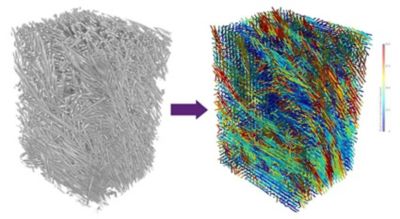
Fiber orientation analysis in Simpleware software of a fiber reinforced plastic (FRP) part.
How to Use the Simpleware Fiber Orientation Analysis
The micro-CT scan projections are reconstructed into a stack of 2D image slices. This stack is imported into Simpleware software. You can use the 3D background volume rendering to visualize the distribution and structure of the fibers within the part. If using distinct ROI, these could also be registered to a larger computer aided design (CAD) model or lower resolution CT scan of the part’s geometry in Simpleware software.
The fiber orientation analysis model is created using the image data, no segmentation is required. Just specify the size of the fibers. This can be measured using a quick distance measurement, and then choose an appropriate sampling size, in voxels, based on the image resolution and your requirements. Now the analysis is ready to run.
Although not required, a segmented region known as a mask representing the fibers can also be added to the analysis. This will focus the analysis by only considering the mask region, making it faster to process in some cases. This is recommended for low filling fractions of fibers and image data with several phases or imaging artefacts.
Displaying the Results
Once the analysis is complete, the results can be displayed though the Statistics tool or the Vectors tool. The statistics tool displays ‘global’ or ‘region of interest’ orientation results, including:
- Principle orientation, this could be used for a homogenized model
- Eigen analysis
- Global orientation tensor
- And more
A series of charts using the fiber orientation calculations can be generated using the Plots tool. These can be tailored to suit your own style and requirements. They include:
- Angle to principle orientation histogram
- Angle to image axis histogram
- Principle orientation hedgehog diagram
- And more
In addition, orientation vectors can be visualized in the 2D slice views and in the 3D view. The vectors show the local principle orientation in that sampling region, overlaid on top of the original image data and any segmented masks. Eigen vectors and ellipsoids can also be plotted in the 3D view giving information on the major, medial and minor vectors in that local region.
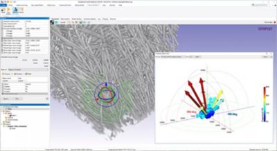
Principle orientation hedgehog diagram applied to a local region of the FRP part.
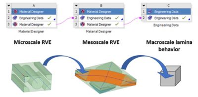
Material Properties for Simulation
The principle orientation can be used as a homogenized material property for initial simulations, enabling you to identify likely regions of high stress and refine your model accordingly. The local principle orientation vectors can be exported to represent local material properties. The vectors are displayed on a coordinate grid based on the image data. This grid is dependent on the sampling size you have selected. The local orientation information is recorded at the center of each grid unit. This can be imported into the simulation software of your choice. The simulation mesh nodes use the closest coordinate grid orientation value for the local material properties.
Using Simpleware fiber orientation analysis enables you to:
- Investigate the manufactured structure of your fibrous or composite structure
- Use statistical analysis to characterize the structure to understand distribution, density and orientation of fibers
- Visualize the principle and local orientation vectors in 2D and 3D
- Export detailed orientation information as material properties for finite element analysis (FEA) to simulate real world performance of your manufactured part
Learn more about Ansys Simpleware software.
The Advantage Blog
The Ansys Advantage blog, featuring contributions from Ansys and other technology experts, keeps you updated on how Ansys simulation is powering innovation that drives human advancement.