Synopsys and Ansys power the future of innovation—connecting silicon to systems.
-
-
Kostenlose Software für Studierende
Ansys unterstützt die nächste Generation von Ingenieur*innen
Studenten erhalten kostenlosen Zugang zu erstklassiger Simulationssoftware.
-
Verbinden Sie sich jetzt mit Ansys!
Gestalten Sie Ihre Zukunft
Stellen Sie eine Verbindung mit Ansys her, um zu erfahren, wie Simulation Ihren nächsten Durchbruch vorantreiben kann.
Kostenlose Demoversionen
Produkte & Dienstleistungen
Lernportal
Über das Unternehmen
Back
Produkte & Dienstleistungen
Back
Lernportal
Ansys unterstützt die nächste Generation von Ingenieur*innen
Studenten erhalten kostenlosen Zugang zu erstklassiger Simulationssoftware.
Back
Über das Unternehmen
Gestalten Sie Ihre Zukunft
Stellen Sie eine Verbindung mit Ansys her, um zu erfahren, wie Simulation Ihren nächsten Durchbruch vorantreiben kann.
Kostenlose Demoversionen
THEMENDETAILS
Was ist Doppelbrechung?
Doppelbrechung (auch optische Anisotropie oder Birefringenz genannt) ist ein optisches Phänomen, das in bestimmten Materialien vorkommt. Die meisten transparenten Materialien verfügen über einen einzelnen Brechungsindex, der den Strahlengang ändert, wenn Licht durch das Material strahlt. In doppelbrechenden Materialien erfährt ein Lichtstrahl jedoch zwei Brechungsindizes, wodurch er in zwei Strahlen aufgespalten wird, die unterschiedlichen Bahnen folgen.
Die Grundprinzipien der Doppelbrechung
Das Phänomen der Birefringenz hängt sowohl von der Struktur des Materials (d. h. vom Atomgitter des Materials) als auch von der Polarisations- und Ausbreitungsrichtung des eingehenden Lichtstrahls ab. Unpolarisiertes Licht, das in ein doppelbrechendes Material eindringt, wird in zwei verschiedene Lichtstrahlen gespalten, die als ordentlicher Strahl und außerordentlicher Strahl bezeichnet werden. Der ordentliche Strahl ist senkrecht (oder orthogonal) zur optischen Achse polarisiert – der Richtung, in der das Licht nicht der Birefringenz unterliegt –, während der außerordentliche Strahl in eine Richtung polarisiert ist, die genaugenommen nicht senkrecht zur optischen Achse ist. Die beiden polarisierten Lichtstrahlen bewegen sich nach der Brechung in verschiedenen Winkeln und Geschwindigkeiten.
Es gibt verschiedene Kristalle, die von Natur aus Anisotropie und doppelbrechendes Verhalten aufweisen. In der Optik bezieht sich Anisotropie auf eine Materialeigenschaft, die je nach der Richtung variiert, in der sie gemessen wird. Einige Materialien mit diesen Eigenschaften sind:
- Calciumcarbonat (Calcit)
- Quartz
- Turmalin
- Rubin
- Titandioxid (Rutil)
- Magnesiumfluorid (Sellait)
Darüber hinaus gibt es einige synthetische Materialien mit nichtkristallinen anisotropen Strukturen, die ebenfalls Doppelbrechung aufweisen können, darunter:
- Fasermaterialien
- Langkettige Polymere
- Harze
- Verbundwerkstoffe
Spannungsdoppelbrechung
Es gibt eine spezifische Art der Doppelbrechung, die als Spannungsdoppelbrechung bezeichnet wird. Diese tritt auf, wenn eine externe Kraft oder Deformation auf ein Material aufgebracht wird. Die Spannungsdoppelbrechung wird durch die spannungsoptische Wirkung verursacht, die normalerweise in Materialien wie Kunststoffen und gedehnten Folien vorkommt.
Wenn Spannung dazukommt, finden Veränderungen auf molekularer Ebene statt, die zu einer ungleichmäßigen Verteilung der Atome und unterschiedlichen mechanischen Eigenschaften führen. Die Wirkung führt dazu, dass sich der Brechungsindex eines Materials unter einer aufgebrachten Spannung oder Last ändert.
Die spannungsoptische Wirkung ähnelt in gewisser Weise dem piezoelektrischen Effekt. Der piezoelektrische Effekt ist ein physikalisches Phänomen, bei dem Materialien unter mechanischer Belastung eine elektrische Ladung erzeugen, während bei der spannungsoptischen Wirkung eine aufgebrachte Last die Ladungsverteilung eines Materials verändert. Statt jedoch die elektrischen Eigenschaften eines Materials zu ändern, ändern sich die optischen Eigenschaften des Materials unter der atomaren Umstrukturierung.
Da Doppelbrechung unter Aufbringung einer mechanischen Last auftritt, ermöglicht sie die visuelle Darstellung der Spannungsverteilung eines Materials. Das ist eine nützliche Art, die aufgebrachten Spannungen und Belastungen an optischen Komponenten zu testen, wenn sie in größere Systeme integriert werden, wie z. B. Headsets für erweiterte und virtuelle Realität (AR/VR).
Beispiele für Doppelbrechung im Einsatz
Es gibt viele wissenschaftliche und technische Anwendungen, in denen Doppelbrechung eingesetzt wird.
Wissenschaftliche Instrumente
Doppelbrechung wird verwendet, um Materialeigenschaften in verschiedenen analytischen Charakterisierungstechniken zu untersuchen, z. B.:
Polarisationsmikroskopie: Bei dieser Technik wird polarisiertes Licht auf eine Probe gerichtet, und die Doppelbrechungseigenschaften der Probe verändern die Polarisation des Lichts. Die Analysatorkomponente in einem Mikroskop kann dann selektiv nur das Licht mit veränderter Polarisation übertragen, was den Bildkontrast erhöht und Informationen über die intrinsischen Eigenschaften der Probe wie Details zu Struktur und Zusammensetzung liefert.
Optische Kohärenztomographie (OCT, Optical Coherence Tomography): Bei dieser Technik wird die Doppelbrechung verschiedener biologischer Materialien, wie z. B. menschlichem Gewebe, verwendet, um Mikroskopaufnahmen mehr Kontrast zu verleihen.
LCD-Bildschirme
LCD-Bildschirme verwenden doppelbrechende Flüssigkristalle zur Anzeige von Bildern und Videos. Diese Flüssigkristalle ändern ihren Brechungsindex, wenn ein elektrisches Feld angelegt wird. Durch die Steuerung der Ausrichtung der Flüssigkristalle kann der Bildschirm sowohl die Polarisation als auch die Intensität des hindurchfallenden Lichts steuern.
Optische Kommunikation
Doppelbrechung wird in Glasfaserkabeln zur Übertragung von Signalen verwendet. Doppelbrechung wird in faseroptischen Komponenten verwendet, die als Wellenlängenumschalter bezeichnet werden. Sie fungieren als optische Gates, die bestimmte Wellenlängen gezielt wählen und auf bestimmte Pfade im Kabel leiten. Doppelbrechende Materialien halten die Polarisation des durchgelassenen Lichts aufrecht, wenn es durch das Kabel geht, was Verzerrungen minimiert und zu zuverlässigeren Kommunikationsleitungen führt.
Polarisationsfilter
Doppelbrechung wird auch in Polarisationsfiltern für Kameras, Mikroskope und andere optische Instrumente verwendet. Polarisationsfilter bestehen aus Materialien mit einer gitterartigen, anisotropen Struktur. Diese steuern, wie Licht mit unterschiedlichen Wellenlängen durchgeht, indem sie eine der beiden Komponenten des polarisierten Lichts blockieren. Dadurch können einzigartige visuelle Effekte sowie Bilder mit geringerer Blendwirkung und höherer Bildschärfe erzeugt werden.
Warum die Messung von Spannungsdoppelbrechung in optischen Werkstoffen wichtig ist
Es gibt viele Bereiche, in denen Doppelbrechung die Funktionalität verbessern kann, wohingegen Spannungsdoppelbrechung die Leistung von optischen Komponenten verringern kann.
In einigen Anwendungen haben Ingenieur*innen bei Linsenmaterialien von Glas auf Kunststoff umgestellt, um optische Systeme leichter und massenproduzierbar zu machen. Polymere wie Acryl und PMMA sind jedoch anfälliger für Spannungsdoppelbrechung. Während der Effekt in Glas nicht so stark ist, kann eine Kunststoffoptik durch Deformation die Interaktion von Licht mit dem Material auf molekularer Ebene verändern. Bei allen Kunststofflinsen, die in Hochleistungstechnologien wie Smartphones, Head-up-Displays (HUD) und AR/VR-Headsets verwendet werden, muss Spannungsdoppelbrechung berücksichtigt werden.
Es gibt zwei Hauptquellen von Spannungsdoppelbrechung bei optischen Geräten: Fertigung und Montage. Bei der Fertigung können Prozesse wie Spritzgießen beim Abkühlen Restspannungen innerhalb der Linse einschließen, da die Außenkanten schneller abkühlen als das Innere.
Wenn eine Linse in ihrer Halterung oder ihrem Gehäuse befestigt wird, können mechanische Spannungen, die durch diesen Prozess verursacht werden, die Verteilung des Brechungsindex innerhalb der Kunststofflinse verändern. Da diese Spannungen die inneren optischen Eigenschaften von Materialien verändern können, müssen sie bei der Simulation und Modellierung berücksichtigt werden, um eine optimale Linsenleistung zu gewährleisten und optische Verluste, wie z. B. Reduzierung von Helligkeit und Intensität, zu minimieren.
Selbst ein Verlust von nur wenigen Prozent der gesamten Lichtdurchlässigkeit kann die Bildqualität und Helligkeit außerhalb der angegebenen Bereiche verringern, wenn sie nicht berücksichtigt wird. Dieser Effekt ist bei HUD und AR/VR-Headsets spürbar, was zu kontrastarmen Bildern führt, die durch eine erhöhte Stromversorgung des Systems ausgeglichen werden müssen. Bei Headsets ist das nicht ideal, da es zusätzliche Wärme erzeugt, die für den Träger unangenehm sein kann, und den Akku schneller entlädt.
Es wird immer ein gewisses Maß an optischen Fehlern geben, die durch Doppelbrechung verursacht werden, aber die Hersteller liefern selten Informationen darüber, wie sich dies auf die optische Leistung ihrer Werkstoffe auswirkt. Mit der Entwicklung fortschrittlicherer optischer Komponenten wird es immer wichtiger, zu verstehen, wie sich Doppelbrechung auf die Leistung verschiedener Materialien auswirkt. Simulation und computergestützte Modellierung können Konstruktionsinformationen liefern, indem sie Multiphysik-Effekte wie Spannungsdoppelbrechung berücksichtigen. Mit ihnen wird die nächste Generation optischer Konstruktionen zugänglich.
Simulieren von Doppelbrechung
Fortschrittliche optische Systeme werden bei Entwicklung, Prototypenerstellung, Tests und Produktion immer teurer. Aus diesem Grund ist eine Reduzierung der Anzahl der physischen Prüfdurchgänge für Prototypen von entscheidender Bedeutung, um die Produktentwicklung voranzutreiben und gleichzeitig das Budget einzuhalten. Dies hilft, Zeit, Aufwand und Geld zu sparen, da sichergestellt wird, dass die ersten physischen Prototypen möglichst genau den vorgesehenen Spezifikationen entsprechen.
Ansys bietet eine Reihe von Tools an, wie die Software Ansys Zemax OpticStudio zur Auslegung und Analyse optischer Systeme und die Software Ansys Mechanical für die Finite-Elemente-Analyse (FEA), um verschiedene Materialien und ihre Doppelbrechungseigenschaften für eine Reihe von optischen Geräten und Endanwendungen zu verstehen. Diese Anwendungen sind auch mit externen Tools wie MATLAB und Moldex3D kompatibel.
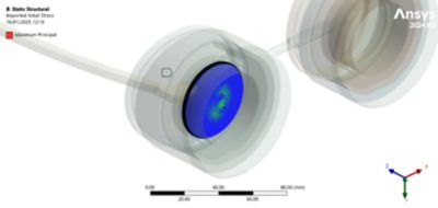
Restspannungen bei VR-Headsets
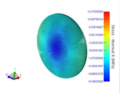
Spannungssimulation bei spritzgegossenen VR-Linsen
Wenden Sie sich noch heute an unser technisches Team, um herauszufinden, wie Lösungen von Ansys Ihnen dabei helfen können, Spannungsdoppelbrechung in fortschrittlichen optischen Systemen zu simulieren.
Zugehörige Ressourcen
Los geht's
Wenn Sie mit technischen Herausforderungen konfrontiert sind, ist unser Team für Sie da. Mit unserer langjährigen Erfahrung und unserem Engagement für Innovation laden wir Sie ein, sich an uns zu wenden. Lassen Sie uns zusammenarbeiten, um Ihre technischen Hindernisse in Chancen für Wachstum und Erfolg zu verwandeln. Kontaktieren Sie uns noch heute, um das Gespräch zu beginnen.