Synopsys and Ansys power the future of innovation—connecting silicon to systems.
-
-
Kostenlose Software für Studierende
Ansys unterstützt die nächste Generation von Ingenieur*innen
Studenten erhalten kostenlosen Zugang zu erstklassiger Simulationssoftware.
-
Verbinden Sie sich jetzt mit Ansys!
Gestalten Sie Ihre Zukunft
Stellen Sie eine Verbindung mit Ansys her, um zu erfahren, wie Simulation Ihren nächsten Durchbruch vorantreiben kann.
Kostenlose Demoversionen
Produkte & Dienstleistungen
Lernportal
Über das Unternehmen
Back
Produkte & Dienstleistungen
Back
Lernportal
Ansys unterstützt die nächste Generation von Ingenieur*innen
Studenten erhalten kostenlosen Zugang zu erstklassiger Simulationssoftware.
Back
Über das Unternehmen
Gestalten Sie Ihre Zukunft
Stellen Sie eine Verbindung mit Ansys her, um zu erfahren, wie Simulation Ihren nächsten Durchbruch vorantreiben kann.
Kostenlose Demoversionen
ANSYS BLOG
February 16, 2023
Simulation Sets New Lightweight Coil Spring Designs In Motion
If your vehicle’s suspension is failing, you’ll definitely know it. The ride can be pretty bouncy — like when a vehicle hits a bump in the road, for example. That impact caused by the wheel hitting the bump pushes the wheel up and the driver receives and feels the force of that impact directly. Essentially, it’s the spring that absorbs the shock, while the shock absorber dampens the energy coming out of this interaction to deliver a more stable ride and help keep all four tires in contact with the road. This is true whether coil springs are supporting vehicles with conventional or electric drive systems.
In an electric vehicle (EV), the weight of a coil spring suspension component can significantly impact performance — all of which are major concerns for original equipment manufacturers (OEMs), Tier One automotive suppliers, and consumers. Mubea Fahrwerksfedern GmbH, an automotive supplier specializing in lightweight vehicle components, looked to Ansys to address these concerns. Using simulation enabled Mubea to optimize its side-load spring designs for both weight and performance in EV suspension applications.
For Mubea, simulation is a key driver for the verification and validation of its automotive suspension components and systems, including its unique spring designs. The reason for simulation is that this spring, also known as the force-medium-point spring, manages live loads in parallel with the ground, so even small design errors can result in significant costs due to vehicle axle damage — errors easily anticipated using simulation.
“For cylindrical coil springs, where the force is applied in parallel, the design can perhaps still be carried out using analytical formulas,” says Sergej Schneider, engineer for simulation technology at Mubea. “However, simulation is essential for the economical and timely design of our springs, which are subject to lateral forces and have various coil spring and deflection shapes.”
Ansys simulation and optimization tools, along with the support from Ansys’ elite channel partner CADFEM, offer Mubea indispensable help in finding the optimum variant for the perfect lightweight component construction.
Unwinding Design Mysteries in a Simulation Environment
Mubea models coil springs with an in-house developed application called GRASP-Designer, which utilizes the mathematical construct of Non-Uniform Rational B-Splines (NURBS). NURBS are generally used to describe complex shapes in 2D or 3D. They are common in computer-aided design (CAD) applications.
The finite element analysis (FEA) required for these components is covered by Ansys Mechanical APDL (Ansys Parametric Design Language). To enable calculations within a simulation environment involves defining the lateral surface of the parametric cylindrical body as a closed NURBS surface, or closed curve that defines the outer border. The incorporation of control points representing this control network operates in the background, enabling further calculations. During the process, not all control points are released as parameters, but rather as a summary of significant points identified in terms of diameter, offset, and inclination, all of which serve to reduce the optimization parameters of the model.
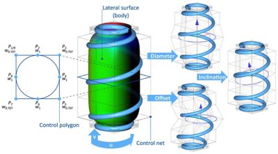
Structure and manipulation of the lateral surface body.
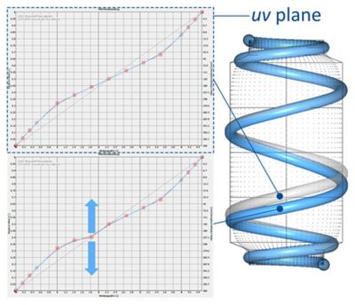
Structure and manipulation of the coiling in the UV plane.
Using a variable number of control points and the corresponding number of coils enables the multi-coiling of the coil spring on the cylindrical body. In this scenario, both the first and last control points are fixed, while others can move freely within the UV plane. The degree of the NURBs curve impacts the local influence of the control point of the coil on the coil spring geometry.
Springing into Optimization with Ansys optiSLang
Once the springs are mathematically modeled, optimization techniques can be introduced into simulation and modeling analysis using Ansys optiSLang. Evaluating different input and output variables helps Mubea achieve a design that meets expectations for weight and performance. Each challenge is solved iteratively, with each iteration moving closer toward an optimized solution.
On the road, coil springs are routinely subject to both static and dynamic loading during compression and extension events as part of the vehicle suspension, and they take up space in the process. Static loading evaluation is based on shear stress, while dynamic loading evaluation is based on a damage parameter. During optimization, restrictions around stress limits, damage, and uniformity of shear stress or damage over a specific area of the coil spring were established to inform material use. Special attention was also given to the point of the spring installation in relation to overall spring size, which helped to anticipate possible damage.
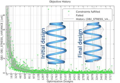
Mubea simulated 4,000 variants in optiSLang to determine the optimal final design.
In the example shown above, a cylindrical coil spring based on an analytical preliminary design was used. Simulation of 4,000 designs in optiSLang was done to achieve the final optimized design. At Mubea, optiSLang is routinely used to check between 4,000 and 6,000 designs to find the best variant quickly and efficiently. For Mubea simulation engineer Sergej Schneider, design optimization with Ansys optiSLang has become indispensable.
“The automated design of coil springs with optiSLang has proven itself to be extremely practical,” says Schneider. “Automated design is convincing in two respects — through high-quality results in the shortest possible time, and by finding sensible solutions, especially where manual design is difficult. The great advantage of automated design lies in the homogenization of the stress and, in particular, damage curves, which otherwise pose a major challenge in manual design.”
See how Ansys Mechanical and Ansys optiSLang enable accurate verification and validation of lightweight components supporting EV applications.