-
-
Kostenlose Software für Studierende
Ansys unterstützt die nächste Generation von Ingenieur*innen
Studenten erhalten kostenlosen Zugang zu erstklassiger Simulationssoftware.
-
Verbinden Sie sich jetzt mit Ansys!
Gestalten Sie Ihre Zukunft
Stellen Sie eine Verbindung mit Ansys her, um zu erfahren, wie Simulation Ihren nächsten Durchbruch vorantreiben kann.
Kostenlose Demoversionen
Produkte & Dienstleistungen
Lernportal
Über das Unternehmen
Back
Produkte & Dienstleistungen
Back
Lernportal
Ansys unterstützt die nächste Generation von Ingenieur*innen
Studenten erhalten kostenlosen Zugang zu erstklassiger Simulationssoftware.
Back
Über das Unternehmen
Gestalten Sie Ihre Zukunft
Stellen Sie eine Verbindung mit Ansys her, um zu erfahren, wie Simulation Ihren nächsten Durchbruch vorantreiben kann.
Kostenlose Demoversionen
ANSYS BLOG
February 21, 2023
An Introduction to Common Antenna Designs
If you’re reading this article on a phone or laptop, there’s an antenna to thank for that. Antennas are an integral part of connecting our lives, making everything from playing video games and powering our car’s navigation systems to nudging asteroids in deep space possible. But while the presence of antennas has become ubiquitous, antenna design and application varies widely.
How do Antennas Work?
From simple wire dipole antennas to phased multiple-input and multiple-output (MIMO) arrays, all antennas do essentially the same thing — send and receive electromagnetic signals. To do this, an electrical signal is turned into a transmissible electromagnetic wave. The information is then sent through the air on a specific wavelength to be received and unpacked by another antenna at the desired destination.
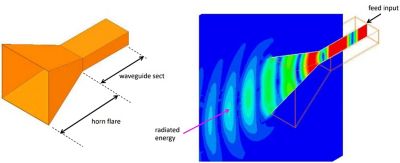
Example of a horn antenna
By sending signals through space, antennas allow us to communicate across great distances at the speed of light. This wireless connectivity has been essential to our advancement across industries, including healthcare, aerospace, communications, and mobility. As the applications for antennas continue to grow, so do the types of antennas needed for every use case.
Why are There Different Types of Antennas?
A variety of factors — such as range and available space — determine the best type of antenna for a given application. For example, the antenna used to keep a plane in contact with the control tower is very different than the one in your Bluetooth coffee mug. Both require an antenna with omni-directional capabilities, but the plane needs much greater range while the mug requires an antenna that conforms to a very small space.
Criteria in Antenna Design
- Bandwidth: the range of frequencies for a particular signal
- Polarization: the direction of the electric fields radiated by the antenna
- Directivity: the degree that radiation is concentrated in a single direction
- Physical space: the size of the area where the antenna must fit
- Gain: how much power is transmitted in the direction of peak radiation
- Efficiency: the ratio of the antenna’s radiated power to its delivered power
Common Antenna Types
Knowing the general characteristics of common antenna types will help you choose the right antenna for your application.
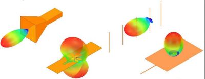
Example antenna types from left to right: horn antenna, slot antenna, Yagi-Uda antenna, and rectangular patch antenna
Half-wave Dipole Antennas
The half-wave dipole is based on the dipole antenna, which is the simplest practical antenna made of two conductive rods or wires. The “half-wave” term refers to the physical size of the antenna being half of a wavelength at the frequency of operation.
Because they are simple to design and make, half-wave dipole antennas are very common. In fact, almost all antennas are based on this design, which has clean, linear polarization and a rotationally symmetric radiation pattern.
A half-wave dipole antenna consists of a linear conductive element of length L = l/2, typically fed by means of a gap inserted halfway along its length. Though they are typically considered a narrowband antenna, increasing the radius of the wire used to form the body of the antenna is an effective method for increasing the bandwidth.
PIFA Antennas
Planar Inverted-F (PIFA) antennas are found in mobile phones and just about every electronic device. A variation of a dipole, these antennas are very inexpensive to make and can be printed in lots of variations to achieve different band widths, making it a good choice for conforming to small spaces.
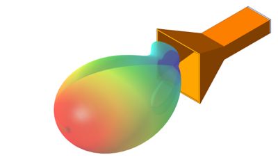
Horn Antennas
Horn antennas are often used in applications that need very high directivity, such as radar guns. They have fairly simple geometry and can handle higher power with less loss.
A horn antenna consists of a section of waveguide that flares outward at the end and terminates in an open aperture. The purpose of the flare is to increase the directivity of the antenna and narrow the beam width in the plane of the flare.
To form the horn of the antenna, horn antennas may be flared only in the direction of the electric field (an E-plane sectoral horn), only in the direction of the magnetic field (an H-plane sectoral horn), or in both directions (a pyramidal horn).
Horn antennas are typically very broadband, operating above the cutoff frequency of the waveguide, and radiate a linearly polarized wave oriented in the same direction as the electric field in the waveguide.
Yagi-Uda Antennas
Sometimes referred to as simply “Yagi” antennas, Yagi-Uda antennas consist of a single dipole antenna which is operated within an array of other (non-driven) linear conducting elements. These are very effective in applications where high directivity is critical and are often used as TV reception antennas.
The exact number of reflectors and directors in a Yagi-Uda antenna varies, but a typical design includes a single “reflector” element and three “director” elements. The reflector element is slightly longer than the dipole, while the director elements are slightly shorter than the dipole.
Unlike an isolated dipole, which has a rotationally symmetric radiation pattern, the Yagi-Uda antenna is highly directive, with its maximum radiation directed toward the directors and away from the reflector.
Like a dipole, a Yagi-Uda antenna is narrowband and has linear polarization, with the electric field oriented in alignment with the dipole.

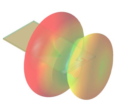
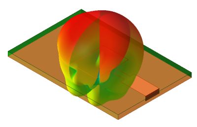
Slot Antennas
Slot antennas are based on the same concepts as dipole antennas, but they use a different set of currents — magnetic instead of electric. They can be found on the nose cones of airplanes and on circuit boards.
Slot antennas consist of a rectangular half-wavelength-long “slot” in an otherwise planar conductor. Operation, by Babinet’s principle, is analogous to that of a half-wave dipole antenna. The radiated fields are also roughly analogous to those of a half-wave dipole antenna, but with the polarizations of the electric and magnetic fields approximately transposed.
The radiation pattern of a slot antenna approximates that of a dipole antenna, but with slight asymmetry introduced by the truncation of the ground plane. Slot antennas have a bandwidth that is variable with the width of the slot and are linearly polarized, with the electric field oriented perpendicularly to the length of the slot.
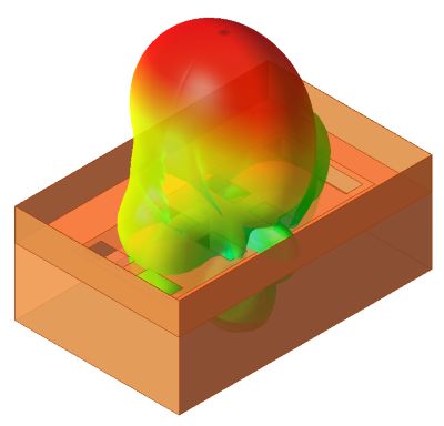
Rectangular Patch Antennas
The most common choice for low-profile applications, rectangular patch antennas are printed to fit into flat spaces such as mobile phones. While the concept of a patch antenna is simple, it can be easily modified to operate at a wider band, increase the isolation, or work on multiple frequencies.
Rectangular patch antennas consist of a rectangular conductive element of width (W) and length (L), which rests on the surface of a dielectric slab of thickness (d) and relative permittivity (er), with conductive backing.
The radiation of the patch antenna occurs due to resonance of the fields in the cavity under the patch. This resonance occurs when the length of the antenna is slightly less than half the length of the guided wave, because field fringing at the ends of the patch makes the patch “appear” longer than it physically is.
Rectangular patch antennas are commonly fed by microstrip, a coaxial probe coming up through the dielectric, or coupling with a resonant cavity or other proximate resonator.
To help determine the best antenna to use in their projects, engineers test and prove their designs using simulation software such as Ansys HFSS. Whether creating satellites, printed circuit boards, or other advanced high-frequency electronics, simulation shows how different antenna configurations will perform.
Learn more by watching the webinar "Base-Station Antenna System Design for 5G/6G Communications."