-
-
Kostenlose Software für Studierende
Ansys unterstützt die nächste Generation von Ingenieur*innen
Studenten erhalten kostenlosen Zugang zu erstklassiger Simulationssoftware.
-
Verbinden Sie sich jetzt mit Ansys!
Gestalten Sie Ihre Zukunft
Stellen Sie eine Verbindung mit Ansys her, um zu erfahren, wie Simulation Ihren nächsten Durchbruch vorantreiben kann.
Kostenlose Demoversionen
Produkte & Dienstleistungen
Lernportal
Über das Unternehmen
Back
Produkte & Dienstleistungen
Back
Lernportal
Ansys unterstützt die nächste Generation von Ingenieur*innen
Studenten erhalten kostenlosen Zugang zu erstklassiger Simulationssoftware.
Back
Über das Unternehmen
Gestalten Sie Ihre Zukunft
Stellen Sie eine Verbindung mit Ansys her, um zu erfahren, wie Simulation Ihren nächsten Durchbruch vorantreiben kann.
Kostenlose Demoversionen
ANSYS BLOG
December 16, 2021
Continental Realizes Greater Workflow Efficiencies in Cantilever Snap Fit Analysis with Ansys Simulations
Within its wide range of products, systems, and solutions Continental Automotive develops heads-up and other displays, instrument clusters, telematic control units, cameras, car keys, and other products that use snap fits as fasteners.
During the product development phase, Continental uses Ansys simulation software to analyze snap fit designs to ensure that:
- The snap fit functions smoothly during assembly
- The assembly stress on the snap fit is within material limits
- The assembly force meets customer requirements
Although nonlinear analysis is required to evaluate snap fit design, this is often reserved for the final design iteration to accommodate lengthy setup times and additional computational resources that can be highly restrictive during design exploration phase.
To circumvent the problems associated with nonlinear analysis, the engineers on the mechanical simulation and validation (MSV) team developed a series of sanity tests that leverage the simplicity of linear analysis to rapidly evaluate a snap-fit design on points (1) and (2).
Snap Fit Nomenclature
There are different types of snap fit options, including cantilever, torsional, and annual snap joints. The cantilever snap fit is the most common. In its simplest form, a cantilever snap fit consists of a protruding beam and a catch that is deflected during the assembly process when the insertion face contacts the mating part (as shown in Figure 1). Once the dwell face on the catch slides past the mating part, the beam flexes back to its original state and the retention face contacts the mating part to securely fasten the assembly.
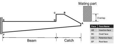
Fig 1
Snap Fit Engineering Workflow
The workflow consists of the three linear analyses (as show in Figure 2). The test loop is performed in sequence starting with bending stiffness and ending with an assessment of the root and catch stress. The test loop is exited if the snap fit design fails during testing. It typically takes less than 10 minutes to evaluate a snap fit design using these linear analysis tests.
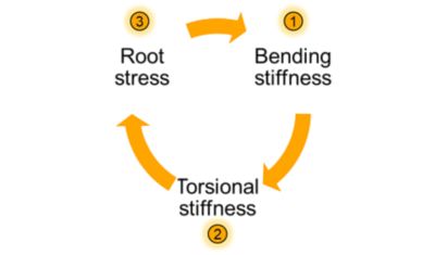
Fig 2
1. Bending Stiffness
Parts may have multiple snap fits with slight variations. For example, some snap fits may have a rib or be shorter in length compared to other snap fits. In either case, the bending stiffness is evaluated to ensure that all snap fits within a part have equal bending stiffness.
To illustrate this concept, consider a part with two snap fits (A and B), as shown in Figure 3. Snap fit A is more flexible compared to snap fit B due its smaller thickness. Assuming both snap fits have similar overlap value during assembly, the bending forces required to deflect snap fits A and B will be unequal. This difference in bending stiffness between snap fits A and B creates a force perpendicular to the direction of assembly (as highlighted in Figure 4). This force not only hinders the smooth functioning of the snap fits during the assembly process, but also results in post-assembly stress, an undesirable outcome causing long-term creep and increased fracture sensitivity of the snap fits.
To evaluate the bending stiffness of the snap fits, each individual snap fit is subjected to a remote displacement boundary condition by the overlap value, while a fixed boundary condition is applied slightly further away from the root (as shown in Figure 3). All other displacement components of the remote load are set to free. For each remote displacement load, a force probe is used to measure the force required to deflect the snap fits to achieve the overlap value. The snap fit design is iterated until the bending forces of each snap fit are equal to other snap fits present in the part (Fbending, A = Fbending, B).
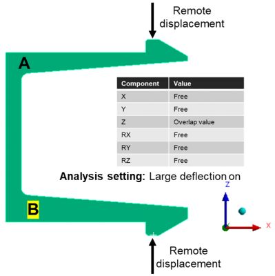
Fig 3
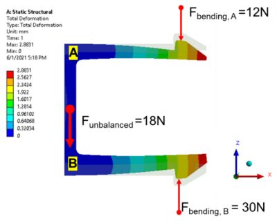
Fig 4
2. Torsional Stiffness
Sometimes it’s necessary to create cuts along the snap fit beam to provide clearance for other components. This cut-out along snap fit beam results in a non-symmetric snap fit (as shown in Figure 5). A non-symmetric snap fit tends to rotate or twist around the longitudinal axis during the assembly process (as shown in Figure 6). Therefore, torsional stiffness of each snap fit must be examined to prevent unwanted twisting.
A snap fit that twists during the assembly process results in stress concentration along the dwell face corners and may create burrs (as shown in Figure 7). Burrs prohibit meeting technical cleanliness requirements.
Evaluating the torsional stiffness of the snap fit does not require any additional analysis. The finite element analysis (FEA) analyst must simply view the deformed catch head on (as shown in Figure 8), and examine it for any rotation of the catch when it is subjected to the remote displacement load described for evaluating the bending stiffness.
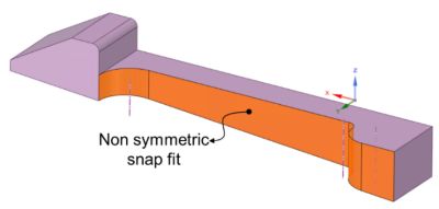
Fig 5
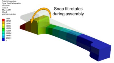
Fig 6
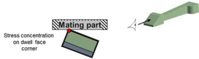
Fig 7
Fig 8
3. Root Stress
The peak stress tensile in a tapered cantilever snap fit occurs at its root. Occasionally a rib is added to the snap fit to enhance its retention force. In this case, the peak tensile stress occurs at the tip of the rib (as shown in Figure 9). During assembly, the dwell face of the catch experiences peak shear stress when the mating part slides over this face. To prevent failure of the snap fit, it is vital that stresses experienced in these key areas are maintained within material limits during the assembly process.
The stress at the root or tip of the rib can be evaluated by subjecting the snap fit to the remote displacement load corresponding to the overlap value, then inserting a stress tool based on tensile strength (for brittle material) or equivalent stress (for ductile material). Should the stress tool identify any hot spots, the cross-section of the snap fit can be examined to verify if the hot spot extends deep into the material, or just surface stress concentration (as show in Figure 10).
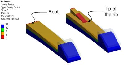
Fig 9
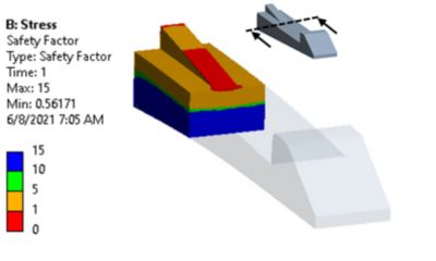
Fig 10
Comparative Study Shows Value of New Simulation Workflow
A comparative study was conducted to determine the time savings and accuracy results between the proposed workflow and a conventional nonlinear analysis. The geometry defined for the comparative study consists of two cantilever snap fits, A and B with an overlap of 2.1 mm (as shown in Figure 11). Snap fit B is stiffer because it has a larger beam thickness. In the nonlinear quasi-static analysis, a coefficient of friction of 0.2 is assumed between the mating parts. To simulate the worst-case scenario, it is assumed that the mating part is rigid. In the static analysis, a remote displacement corresponding to the overlap value of 2.1 mm has been applied to the dwell faces of snap fits A and B.
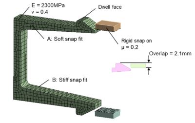
Fig 11
The main nonlinear contact parameters used for nonlinear analysis are defined in Figure 12. As shown in Figure 13, the penetration of the nonlinear contacts is kept within 2% of the snap fit overlap value of 2.1 mm to ensure accurate results.
The results of the comparative study show that the bending force differences determined by the two methods are largely in agreement (less than 2N). The location of the maximum equivalent stress is also similar in both analyses. The magnitude of the maximum equivalent stress is slightly lower (~5MPa) in the case of the static analysis; however, this accuracy is acceptable during the initial design evaluation and exploration phase. In general, it can be concluded that the static analysis proposed by the workflow gives a similar difference in bending force and equivalent stress at the root as that of the nonlinear analysis. The time and effort required for the static analysis is minuscule in comparison to the nonlinear analysis.
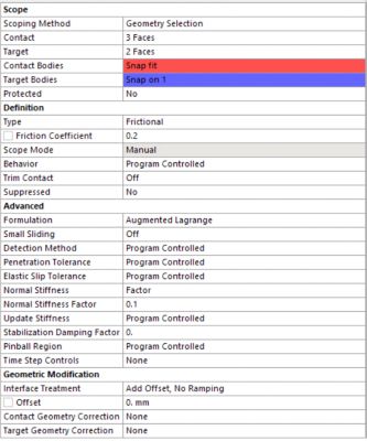
Fig 12
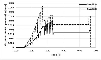
Fig 13
The CPU time required to solve the static analysis is nine seconds, while a CPU time of 187 seconds was recorded in the case of nonlinear analysis. Therefore, the proposed workflow resulted not only in a simple setup, but also a 95% reduced time-to-solution.
Snap Fit Simulation Sanity Test Conclusion
A snap fit that passes all three sanity tests will not only function smoothly during the assembly process, it will also have a low risk of structural failure. Because these tests are static linear analyses, quick solutions can be offered, and multiple design iterations can be explored. A snap fit design that clears these sanity tests can then be subjected to advanced nonlinear analysis to ensure that the assembly force meets customer specifications.
Learn how Ansys Discovery can revitalize your product development workflows. Try it for free today!