-
-
Access Free Student Software
Ansys empowers the next generation of engineers
Students get free access to world-class simulation software.
-
Connect with Ansys Now!
Design your future
Connect with Ansys to explore how simulation can power your next breakthrough.
Free Trials
Products & Services
Learn
About
Back
Products & Services
Back
Learn
Ansys empowers the next generation of engineers
Students get free access to world-class simulation software.
Back
About
Design your future
Connect with Ansys to explore how simulation can power your next breakthrough.
Free Trials
ANSYS BLOG
August 31, 2021
Using Litz Wire in Maxwell 2D and 3D Simulations
Litz wire is often used in power conversion equipment to reduce induced alternating current (AC) losses in conductors. Litz wire consists of many insulated strands or filaments, which are connected electrically in parallel and continuously transposed. This type of conductor has nearly the same direct current (DC) resistance and overall current carrying area as a single solid wire but the AC induced losses (both skin effect and proximity effect) are reduced due to the smaller cross-sectional area of individual strands versus a single solid strand.
Ansys Maxwell now has the capability to analyze Litz wire. Because a Litz wire bundle can contain hundreds or even thousands of small strands, it is difficult (or impossible) to model every strand explicitly using finite element analysis (FEA). Therefore, a Litz bundle is modeled as a single object with the same outer diameter.

Fig. 1. Representation of a Litz bundle in Ansys Maxwell for round wire
There are many types of Litz wire configurations such as round, rectangular and square. Using Maxwell, Litz wire is defined in the material properties with the number of strands and their exact size.
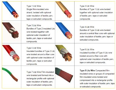
Fig. 2. Types of Litz wire
To model Litz wire in the Maxwell 2D and 3D Eddy Current or Transient Magnetic solvers:
- Litz conductors are defined as a material where strand size and number of strands are specified.
- The Litz bundles are modeled as a single object.
- Eddy effects are OFF in the object.
- Magnetic fields induces proximity losses in conductors, but these losses do not impact the source field.
- Loss calculation is valid assuming the thickness of strands ≤ skin depth.
- Losses are calculated due to: Bx, By, Bz and J (for frequency domain) and dBx/dt, dBy/dt, dBz/dt and dJ/dt (for time domain).
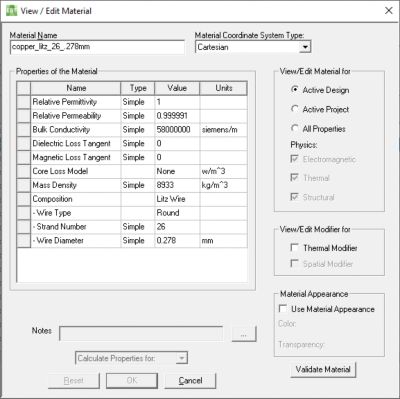
Fig. 3. Litz wire material specification for round wire
The distance required for a particular strand to be completely transposed is called the “lay-length.” Usually, this distance is equivalent to 15-20 times the diameter of an individual strand. With this continuous transposition, the lengths — and DC resistances — of the individual strands are essentially equal. In addition, each strand theoretically sees the same flux linkage so that circulating currents are minimized and effectively prevented.
As shown in the gapped inductor example below, the loss density in Litz wire considers the effect of proximity losses due to fringing flux. Because the number of Litz strands was relatively small for this example, they were also modeled with each strand drawn explicitly. This was then compared to 2D and 3D models, having Litz wire where the loss density plots are essentially the same.
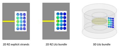
Fig. 4. Comparison of explicit strand model vs. Litz wire bundle
Finally, the AC resistance of the Litz conductor is calculated from the resulting losses and then reported in the impedance matrix.
In summary, Maxwell’s capability to simulate Litz wire provides magnetic designers with a powerful tool to understand the benefit of using Litz wire. AC losses and resistance are calculated directly using FAE as opposed to relying on less accurate empirical or analytical equations. Litz wire can even be considered in a two-way magnetic-thermal analysis to determine the steady-state operating temperature while taking temperature dependent material properties in to account.