-
-
Access Free Student Software
Ansys empowers the next generation of engineers
Students get free access to world-class simulation software.
-
Connect with Ansys Now!
Design your future
Connect with Ansys to explore how simulation can power your next breakthrough.
Countries & Regions
Free Trials
Products & Services
Learn
About
Back
Products & Services
Back
Learn
Ansys empowers the next generation of engineers
Students get free access to world-class simulation software.
Back
About
Design your future
Connect with Ansys to explore how simulation can power your next breakthrough.
Free Trials
Ansys Blog
June 13, 2019
Thermal Degradation of Electronics: How Hot is Too Hot?
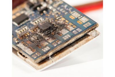
Power supplies are the heart of every electronic device, but it’s difficult to know how cool they need to operate to avoid thermal degradation of neighboring components.
Due to indirect communications between design teams and suppliers, it’s often more difficult to know what the temperature should be than what it will be.
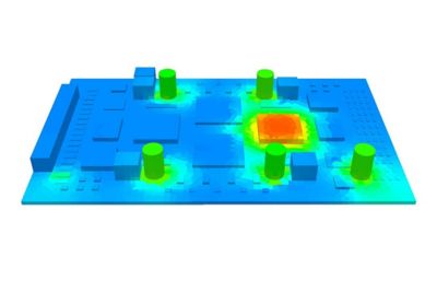
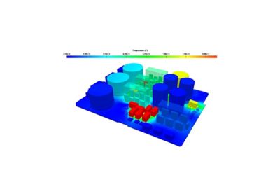
A heat map made using Sherlock
The electronics industry is realizing that derating strategies are not the best methods for designing optimal electronics. The broad assumptions of derating strategies can result in conservative, expensive designs or designs with insufficient reliability.
A more effective approach is one that uses simulation and physics-based analysis to ensure the reliability of components that are susceptible to temperature degradation. For example, engineers can use Ansys Icepak to perform thermal simulations and Ansys Sherlock to build on those simulations to provide physics-based reliability analyses.
Thermal Degradation of Magnetics
Magnetics, such as transformers and chokes, are often not considered when temperature concerns arise during design reviews. Since transformers are typically custom made, many do not come with a temperature rating.
So, how do you determine when it is too hot for magnetics? There are three key issues of concern which can all be solved using simulation software.
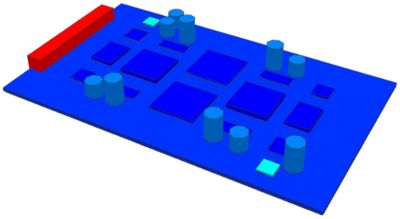
Sherlock thermal derating
The first is that the current saturation curves for ferrite materials tend to obscure when these materials starts to saturate. Saturating the magnetic material will not damage a magnetic, but it will appear to be shorted — causing the circuitry to fail.
The second issue is that designers sometimes mistake a magnetic’s maximum temperature rating as being equal to the Curie temperature (when a magnet’s properties change considerably at around 100 C – 300 C or 212 F – 527 F). However, core loss (magnetic alterations) usually begins at temperatures between 50 C – 100 C (122 F – 212 F). Depending on the ferrite design, structure and cooling, the magnetic can go into a thermal runaway if the core temperature gets into the core loss range.
Finally, thermal aging is a primary concern for powder iron cores — which are lower cost and sometimes more appropriate than ferrite cores. Long-term exposure to elevated temperatures can induce thermal aging of the binding agents. As thermal aging progresses, the eddy current loss becomes significantly higher. Increasing core loss results in higher core temperatures and failure of the magnetic component.
Thermal Degradation of Light Emitting Diodes/Optocouplers
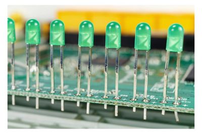
Simulations can help engineers optimize the placement of LEDs into electronics based on thermal stress.
LEDs are used as indicators when they are incorporated into power supplies. However, this incorporation can be tricky because of LEDs’ sensitivity to temperature.
There are also challenges when LEDs are used in optocouplers — components that transfer information through light. The primary challenge is to locate the optocoupler where the LED can stay cool.
LEDs must be positioned on a
chip so they do not experience
too much heat
Thermal Degradation of Electrolytic Capacitors
Electrolytic capacitors are the components designers need to be most concerned about with regards to temperature. This is because electrolytic capacitors rely on liquid for functional operation. The lifespans of these components are limited by the gradual evaporation of their liquid electrolytes.
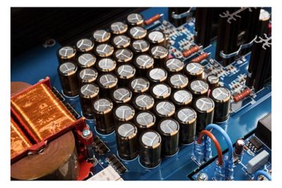
Engineers need to determine if this is an optimal orientation for
these electrolytic capacitors
This loss of electrolytes leads to decreasing capacitance and increasing equivalent series resistance. As a result of this process, all electrolytic capacitor manufacturers provide a rated lifetime.
The capacitors’ sensitivity to heat stresses the importance of highly accurate tools, like simulation, to determine the temperatures that electrolytic capacitors experience.
Nonetheless, most companies extrapolate a manufacturer’s ratings using a classical Arrhenius equation. The equation develops a conservative prediction of the capacitor’s lifetime that is hit-or-miss.
Additionally, the actual lifetime of the capacitor can vary depending upon the sensitivity of the circuit to changes in component parameters. The manufacturers’ definition of lifetime is typically a 20% drop in capacitance. However, at that point the equivalent series resistance could experience an increase of 2X to 5X. Depending on the sensitivity of the circuit, this could induce failure in the product before the capacitor is considered to be in failure mode.
When designers place electrolytic capacitors near hot components, the standard lifetime equation may not even apply as non-uniform temperature distributions across the capacitor can induce accelerated degradation and pressure increases that can induce rupture.
Thermal Degradation of Ceramic Capacitors
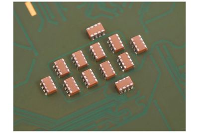
Ceramic capacitor manufacturers have aggressively increased the capacitance of their products. This improvement requires the capacitor to have more dielectric layers, each with a reduced thickness.
However, the voltage hasn’t been able to keep up with the changing thickness of the capacitor’s dielectric layers, resulting in a significantly higher electric field across the dielectric.
A combination of accelerated testing determined that various capacitors types (0603/10 uF/6.3 V/X5R) operating at 40 C (104 F) and 3.3 VDC could see a two percent failure rate after 10 years.
Thermal degradation analysis is
needed to determine if these
ceramic capacitors can survive
this placement on the PCB
Two percent may not sound like much, but once you consider all of the capacitors in your design, simulation starts to sound like a good investment to solve the problem.
Thermal Degradation of Film Capacitors
Film capacitors can fail by one of two mechanisms, both of which are sensitive to temperature:
- Partial discharge
- Embrittlement of the dielectric material
Unfortunately, there aren’t any formulas that effectively separate the effect of two distinct failure mechanisms. The typical approach to predict the capacitor’s lifetime is to extrapolate from standard IEC 60384-16 endurance tests. However, simulation can make these predictions with more accuracy.
The lifetime of film capacitors is by far the most sensitive to variations in voltage. Designers are willing to allow film capacitors to get a little hotter than electrolytics or ceramics, because sufficient voltage derating can extend the lifetime of most applications.
Thermal Degradation of Integrated Circuits
Engineers need to investigate the effects of environmental conditions on integrated circuits to ensure they don’t wearout during their intended lifecycle.
Engineers can assess the thermal reliability of integrated circuits
using reliability physics analysis and failure mechanism models
The main concerns are the submicron processes that drive wearout. The ability to analyze the thermal effects that impact failure mechanisms and device reliability is necessary to mitigate the risk of system degradation.
Engineers can assess their integrated circuits using reliability physics analysis, simulation and failure mechanism models.
Thermal Degradation of Solder Joints
Solder joints provide electrical, thermal and mechanical connections between components, substrates or boards.
When experiencing changes in temperature, the components and boards will expand or contract at different rates — placing the solder joint under shear loads.
This stress is typically far below the strength of the solder joint.
Engineers can ensure the success
of these solder joints using simulation
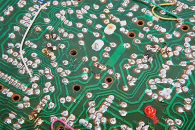
However, repeated exposure to temperature changes can introduce damage in the bulk solder. Simulation can be used to model how each additional temperature cycle will accumulate damage, leading to cracks and eventual failure.
The failure of solder joints due to thermomechanical fatigue is one of the primary wearout mechanisms in electronic products. This is because inappropriate designs, material selections and environments can result in relatively short times to failure.
Finding a Solution to Thermal Degradation
While it’s clear that thermal degradation is an issue, power supply engineers have a challenging time resolving them due to a lack of effective tools.
A viable approach is to utilize reliability physics analysis and simulations. These simulations can predict degradation behavior so engineers can perform tradeoff analyses. These tradeoff analyses will help the engineer optimize the electronics’ environment, material and architecture.
Thermal mechanical analysis
Engineers can also use this information to provide accurate predictions of the power supply’s thermal performance.
Ansys Sherlock Automated Design Analysis software helps power supply engineers understand when a component is too hot. It combines standard design information with comprehensive embedded databases to provide the inputs necessary to perform these complex calculations.
Sherlock’s streamlined software architecture also ensures that the thousands of calculations needed to complete and display these results are done within a matter of minutes. Most importantly, this analysis can be performed by the design team well before physical prototyping — reducing budgets and time to market.
By using Sherlock, power supply engineers can now be sure that their product will never be too hot. To learn more, download the white paper Thermal Management Solutions: How Hot is Too Hot?
Or read the blog, Ansys' Acquisition of DfR Solutions Will Help Ensure the Reliability of Electronic Systems and Components.
