-
-
Access Free Student Software
Ansys empowers the next generation of engineers
Students get free access to world-class simulation software.
-
Connect with Ansys Now!
Design your future
Connect with Ansys to explore how simulation can power your next breakthrough.
Free Trials
Products & Services
Learn
About
Back
Products & Services
Back
Learn
Ansys empowers the next generation of engineers
Students get free access to world-class simulation software.
Back
About
Design your future
Connect with Ansys to explore how simulation can power your next breakthrough.
Free Trials
ANSYS BLOG
April 16, 2021
How to Model and Simulate Complex Electric Motors
For many years, the best practices to prepare a 3D model for simulation involved first importing 3D geometry, then defining the smallest circumferential symmetry. In the case of radial field design, we would first separate the symmetric 3D design (3D slice) from the rest of the 3D geometry by two radial planar cuts, which would later be used to define the boundary conditions to assign such symmetry. This is still a modern approach, largely used in the simulation industry to narrow down the simulation design space and reduce the total computation time required by already expensive time-stepping analysis. Due to this space reduction, the mesh maker can deploy more symmetric and regular mesh topologies to minimize the numerical method impact (finite element) to the overall prediction of motor performance, which is good.
However, the challenges encountered by designers when 3D geometry becomes more complex have yet to be addressed. 3D designs with skew rotor and/or stator configurations (see below) and their electric motor topologies require a compromise between smallest valid geometric symmetry and the required electromagnetic conditions. Despite the symmetry used to compute the motor performance, any designer would also prefer to get the field solution displayed back onto the entire 3D geometry.
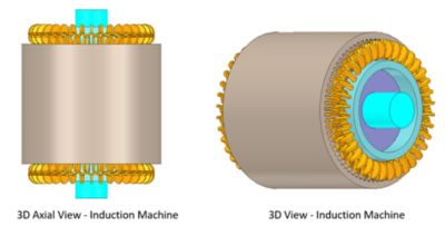
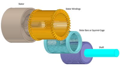
Complex 3D geometry of motor components
3D electromagnetic problems become more complex in multiphysics simulations such as noise-vibration and harshness (NVH). Thermal management presents another set of problems where the entire 3D design space solution might be required to satisfy the specific physics conditions.
How Designers Deal With Complex 3D Geometries Today
There are a number of drawbacks associated with how designers typically approach complex 3D geometries.
For instance, importing computer-aided design (CAD) geometries might also bring in details that aren’t necessary for electromagnetic simulation, which would then require time to remove. Creating the geometry from scratch would require CAD skills as well as associated time and costs.
As mentioned previously, defining circumferential symmetry (3D-slice) by creating radial planar cuts do not always capture the correct symmetry in the geometry, especially when the motor shows skew configurations. Planar cuts mandate separation of the 3D-slice model from the rest of the geometry, which makes it difficult to transfer electromagnetic data (losses or forces) onto the full 3D geometry when thermal management or NVH analyses are required as multiphysics coupled designs.
Finally, manually assigning mesh operations to ensure simulation accuracy requires knowledge about the mesh impact on the FEA solution.
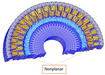
Field calculation on a circumferential symmetry using automatic nonplanar boundary conditions
Targeting these challenges, Ansys Maxwell has introduced a best-in-class solution in 2021 R1. It allows engineers to import an entire 3D motor geometry from any CAD tool. Maxwell automatically creates the 3D circumferential slice-based model, applying nonplanar cuts as boundary conditions and corresponding regular and symmetric mesh (clone mesh) on all parts of the geometry.
This approach allows Maxwell to solve only a fraction of the original 3D space and display field results back onto the initial 3D geometry. Moreover, solving electromagnetics on newly reduced space designs, Maxwell allows coupling with thermal solvers and a structural harmonic solver where the full 3D geometry is required, imposed by the nature of different physics. The ultimate secret to this method and the benefit to the customer is the application of non-planar cutting boundaries to assign proper electromagnetic symmetry in the much-reduced design space. This gives you the most accurate and symmetric mesh of even the skew rotors and stators without increasing the computation cost.
Without a doubt, the new methodology is becoming the new best practice for motor design simulation of complex 3D geometries. This is a powerful solution that allows entry- or senior-level engineers to work on a project quickly and solve models with record speed and accuracy.
Learn about this solution and much more that Ansys Maxwell brings in 2021 R1 release in this in the on-demand webinar: More Detailed Simulation for Electric Drive Applications.
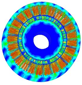
Fields display on full circumferential showing magnetic flux density and current density.