-
-
Access Free Student Software
Ansys empowers the next generation of engineers
Students get free access to world-class simulation software.
-
Connect with Ansys Now!
Design your future
Connect with Ansys to explore how simulation can power your next breakthrough.
Countries & Regions
Free Trials
Products & Services
Learn
About
Back
Products & Services
Back
Learn
Ansys empowers the next generation of engineers
Students get free access to world-class simulation software.
Back
About
Design your future
Connect with Ansys to explore how simulation can power your next breakthrough.
Free Trials
ANSYS BLOG
March 29, 2023
What is Electromagnetic Coupling?
Electromagnetic coupling occurs when the electromagnetic field (E-field component) produced by one circuit element, such as a transistor, interacts with another circuit element. This interaction results in the transfer of energy between the two elements, which affects the operation of the integrated circuits.
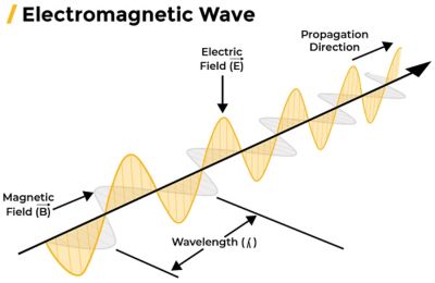
Electromagnetic Interference (EMI) occurs because of a close relationship between electricity and magnetism. An electromagnetic wave consists of electric and magnetic waves running perpendicular to each other. Each component responds differently to frequency, voltage, current and distance, but with recent advancements in designing electronic systems, the E-field factor is mainly responsible for interference.
EMI can also occur because all electrical conductors act as an antenna at high frequencies. A wire will start emitting significant electromagnetic energy as its length approaches half the wavelength of the signal frequency it carries. Thus, at low frequencies, wires need to be quite long before significant electromagnetic emissions occur. But at high frequencies, even very short wires act as antennas. As the switching speed of transistors increases, the probability of electromagnetic coupling increases, and transistors become the major source of Electromagnetic noise. The radiated signals should be below the accepted level to ensure the functionality and performance of the chip.
Causes of EMI Coupling
To determine the cause of EMI coupling, it’s most important to understand how it is coupled from source to receiver. There are four methods of EMI coupling: conduction, radiation, capacitive, and inductive.
Conduction
When EMI is emitted along conducting wires or electrical routes in a design that connects the source and receiver, it is considered conductive coupling. Conductive coupling often happens on power distribution lines. Conductive coupling can be either common mode or differential mode conduction, depending upon the connection technique. For example, if you turn on the mixer in your kitchen, this may cause a disturbance on your television screen because both are connected to the same electrical line. The most effective solution to conduction coupling is shielding the wires and using filters.
Radiation
EMI through radiation doesn’t require any physical connection between the source and receiver. Radiation coupling usually occurs at higher frequencies, when the unwanted electromagnetic signals are radiated from the circuit operating at high frequency and received by a different chip or circuit nearby. For example, whenever you take off or land in an airplane, you are requested to turn off your electronic devices because electromagnetic radiation from electronics can interfere with airplanes’ electronic devices and systems. Radiation coupling can disrupt proper functioning or cause malfunction.
Capacitive Coupling
The electric field component is responsible for capacitive coupling, whereas magnetism is responsible for inductive coupling. Capacitive coupling happens when two conductors are running very close to each other. The changing voltage in the source capacitively transfers the charge to the victim conductor. This mostly happens on closely routed signals on the chip, in which the electronic circuits are closely packed.
Inductive Coupling
Inductive coupling depends upon the magnetic field generated by the source around the victim conductor. The changes in the magnetic field results in inducing unwanted current in the nearby victim conductor. Inductive coupling occurs when two circuit elements are in close proximity to each other but are not directly connected. However, much longer-range inductive coupling is possible, especially with conductive rings surrounding a source.
Advantages of Electromagnetic coupling
Transformers and Inductors: Electromagnetic coupling is the basis of operation for transformers and inductors in any electronic circuit. Transformers facilitate voltage regulation and power transfer between different circuits, while inductors store energy in magnetic fields and filter out unwanted frequencies.
Data Transfer: Electromagnetic coupling is used in technologies like near-field communication (NFC) and inductive data transfer, enabling quick and secure data exchange.
Inductive charging: Electromagnetic coupling is utilized in inductive charging systems, such as wireless charging pads for smartphones and other electronic devices.
Disadvantages of Electromagnetic coupling
Crosstalk: The unwanted electromagnetic coupling between signals running parallel to each other is called crosstalk. This can lead to signal integrity issues, which cause data corruption and degrades circuit performance.
Noise and Interference: Electromagnetic coupling can introduce unwanted noise and interference into sensitive circuits. The generation of noise by digital circuits can cause interference with the analog section, posing a serious risk to the overall circuit performance. This interference can degrade signal quality, resulting in errors and malfunctions within the IC.
Signal Integrity Issues: High-frequency signals are particularly susceptible to electromagnetic coupling, leading to signal integrity problems such as reflections, ringing, and attenuation. This can affect the overall reliability and performance of the IC.
Emissions from IC: Electromagnetic coupling can result in the emission of electromagnetic radiation from the IC. This may cause electromagnetic interference (EMI) with other nearby electronic devices and systems, leading to compliance issues with electromagnetic compatibility (EMC) standards.
EMI Susceptibility: Integrated circuits are also susceptible to external electromagnetic interference due to their small size and high circuit density. This can result in malfunctions or disruptions in the IC's operation.
How to Mitigate the Effects of EMI Coupling
The fast growth of electronic technologies in the last few years is making designers create compact, efficient, and very high-speed chip designs. This has led to major challenges for chip designers, one of which is EMI issues. EMI directly affects the performance and reliability of chips. The E-field factor of EMI is mainly responsible for the coupling of unwanted signals between the circuits.
To mitigate the effects of electromagnetic coupling in chip design, designers use multiple techniques. Shielding is one popular technique to avoid electromagnetic interference in high-speed chips like RF ICs. Shields absorb or block the E-fields, preventing unwanted signals from interacting with sensitive circuit elements such as transistors, antennae, or other active devices. Shielding can be implemented in a number of ways, including the use of enclosures made from conductive materials or the use of conductive materials as layers within a circuit board.
Another technique for mitigating electromagnetic coupling is using predefined high-speed layout techniques and advanced simulation methods. Since chips are designed at very high speed and use high data rate signals, these techniques aren’t enough to ensure electromagnetic compatibility (EMC). It’s important to predict the electromagnetic coupling behavior of integrated circuits using advanced simulation methods. Ansys provides a complete suite of electromagnetic simulation tools that can synthesize inductors and predict the EMI behavior of RF ICs and sign-off. The automation and modeling capabilities of the tools enable designers to design at faster data rates with higher fidelity.
Electromagnetic coupling is an important issue in advanced high-speed chip designs, as it can affect the performance and reliability of electronic circuits. It’s always important to follow layout guidelines and use shields, filters, and other devices, but predicting its behavior in the real world can only be possible through use of simulation tools. Ansys provides best-in-class technology to analyze EMI in order to produce high-quality chips that meet the performance and reliability requirements of their intended applications.
By understanding the principles of electromagnetic coupling and implementing effective techniques to mitigate its effects, chip designers can produce circuits that are able to operate reliably and achieve their desired performance levels.
To learn about EMI’s role in automotive applications, read the blog Ensuring Electromagnetic Compatibility of Integrated Circuits for Automotive Applications.
Or learn more about Ansys RaptorH, Ansys’ high-capacity EM simulation tool.