Synopsys and Ansys power the future of innovation—connecting silicon to systems.
TOPIC DETAILS
What is System Simulation?
System simulation is the process of creating a mathematical model of a real-world system and then varying inputs to observe how changes in those inputs affect the system and its outputs. Those observations are then used to understand the interactions between multidomain subsystems, the effect of those interactions on each other, and the overall system performance. This approach can be applied to any complex system, though in most cases the term refers to creating and exercising a simulation model of a physical system. The systems engineering industry defines a system as: “A combination of interacting elements organized to achieve one or more stated purposes.”
Also referred to as systems simulations or system-level simulation, engineers use this form of virtual prototyping to understand complex systems that include machinery, electronics, software, human operators, and fluid or solid materials moving through or around the system. The goal of exercising system models is to understand how the components interact to perform the desired actions and how that interaction impacts each component, often called system behavior. System models run quickly, as close to real time as possible.
The Benefits of Using System Simulation
Detailed or component-level simulation focuses on individual components or assemblies with finite element analysis (FEA) or computational fluid dynamics (CFD) tools. However, as devices have become more complex, combining multiple physics, control systems, and increasing levels of automation, systems engineers have developed simulation models that view the devices under study at a higher level, capturing the interactions between components.
System simulation supports the entire design process. It starts by providing engineers with a tool that lets them explore their product early in the design cycle when the details are not known. At this point, they can make architectural decisions and explore trade-offs. The system model also provides the requirements and boundary conditions needed for component-level design. Then, later in the design process, system simulation provides system-level verification and validation of the design, ultimately providing the foundation for digital twin models that support the operations phase of the product. Engineers run system simulations to better understand how their products behave as a system throughout the product life cycle. This information helps with informed decision-making that generally leads to four benefits:
- Lower Product Development Costs: Without system simulation, engineers can’t identify system-level issues in their design until the end of the development cycle, when they have assembled a prototype and tested it. System simulation for systems engineering takes place on the project definition, or left side, of the V-model when the cost of change is lowest.
- Time to Market: Not only is virtual prototyping faster for product validation than building and testing real-world prototypes, but system simulations enable engineers across disciplines to work in parallel, getting a working product to market faster.
- Increased Product Performance: The most significant benefit of system engineering is optimizing system performance. The quick system simulation run times enable engineers to use system models to reduce production costs, improve quality, increase throughput, enhance efficiency, and extend the time between component repairs and replacements.
- Decreased Operating Cost: A key performance metric is the system's operating cost. Because system simulations tend to run quickly, they can assess a system’s behavior over its lifetime, a difficult task in physical testing. By applying different test scenarios, engineers can use simulation software to evaluate the effects of component or system modifications to reduce operating costs.
Applications for System Simulation
Because so many devices today are systems with multiple components that interact in complex ways, engineers across industries use system simulation. However, a few industries have made systems-focused simulation processes central to their system design. A look at a few of these gives a good overview of how teams use system simulation.
- Telecommunications: Telecommunications pioneered systems engineering to model the intricate network of telephones. Now that the industry has moved to fiber optics, satellite, microwave, and cellular networks, the complexity of the system models used has increased. The industry uses it for network planning to help determine where to put transmitters and how to connect the nodes in the network.
- Automotive Engineering: Automobiles have always been systems, but modern vehicles are now elaborate systems with electrical and mechanical components managed by communication networks. Automotive engineers use model-based systems engineering (MBSE) for safety systems and electric powertrains, 1-D fluid networks for fuel and cooling flows, and multibody dynamics simulations for suspension and steering.
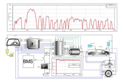
An image from the Ansys Twin Builder simulation-based digital twin platform of an electric car powertrain
- Aerospace Engineering: The systems that support aircraft and spacecraft use are also heavy users of systems engineering. Along with uses in the automotive industry, 1-D models are used to represent cooling inside and outside the vehicle, for mission simulation in RF communications optimization, and for significant control system modeling.
- Industrial Equipment: Another good case study for the effective use of system simulation is the industrial equipment used in modern manufacturing facilities. Engineers use system modeling of these complex machines, or multiple machines in a production line, to search for and remove inefficiencies, to train artificial intelligence (AI) models that use machine learning, and for predictive maintenance.
- Financial Markets: Financial markets are a great example of an industry that uses system simulation outside of modeling physical systems. But financial markets are just as complicated, and analysts can use a 1-D network that solves with the same numerical methods. The most common applications of system-level models in the financial world are predicting how an investment portfolio might perform using stochastic modeling or stress-testing how a bank or a system of banks might respond to a crisis.
System Simulation and Digital Twins Across Industries
A growing use of system simulation is in the area of digital twins. A digital twin is defined as a virtual representation of real-world entities and processes, synchronized at a specified frequency and fidelity. Where a standard system simulation drives the design process, digital twins are virtual representations of operating systems. Engineers use system simulations when accurate physics modeling is required. These model-based virtual systems have an advantage over data-driven models because they can predict behavior that has never occurred.
Although digital twins can use detailed component models when appropriate, they usually include system simulations because they solve problems so quickly, a requirement for most digital twin implementations. This is especially true when pairing digital twins with industrial Internet of Things (IoT) applications, where tools pair a virtual model with real-time data acquisition. Engineers are finding that hybrid digital twin models that combine data and simulation offer significant advantages for accessing actionable information and optimizing systems.
The Different Types of System Simulation
Engineers classify system simulation in many ways. In most cases, they separate approaches by the physics involved, the representation of time in the algorithms, the role of input randomness, and dimensionality.
Although not part of the typical definition, many forms of system simulation also include modeling the software that is interacting with the system. Systems engineers conduct control system simulations using a system model of the devices that the software manages. They also include software to manage inputs and process outputs from their models.
Here is a list of the types of simulation used to model systems:
Physics Modeling
The most common way to classify system simulation approaches is by the physics they represent, because the physics determines the inputs, the equations, and the outputs used to represent each component. In many cases, engineers need to use some form of multiphysics simulation to capture their system’s behavior:
- Electrical and Electronic System Simulation: From chips through printed circuit boards (PCBs) to a power substation, electrical devices are, by definition, networks of components and therefore systems. The goal here is to understand current, voltage, and resistance in the system as electrons flow. The origins of systems engineering began at Bell Labs, where engineers needed to understand the electrical network that was the phone system. They used analog mathematical models to simulate these systems.
- Fluid System Simulation: Fluids rarely remain in a single component. Gases and liquids move between components, changing velocity, pressure, density, temperature, or composition. This system simulation models each component in terms of how it changes the fluid between input and output.
- Mechanical System Simulation: The focus of mechanical system simulation is to capture the positions, velocities, and accelerations of physical bodies, along with the forces acting on and between them. The automotive industry was the innovator in this form of physical modeling, using multibody dynamics to better understand automotive suspension.
- Optical System Simulation: Cameras and other optical sensors are everywhere, and many systems use light to transfer information. And just as fluids do, light usually travels through a series of components to perform a task. Optics engineers use optical system simulation to measure the path, frequency, and amplitude of light.
- Multiphysics System Simulation: As mentioned above, most of today’s systems involve one or more physics. From a systems modeling perspective, that means that the outputs of one physics become the inputs to another physics in the system. Multiphysics system models also often use co-simulation, where a full model of a given physics is included in the system model, rather than a simplified representation. Some of the more common simulation workflows that cover multiple physics include:
- Electro-mechanical simulation
- Fluid-mechanical simulation
- Process simulation (supply chain, manufacturing, material processing, financial markets, etc.)
- Optomechanical simulation
- Photonics
- Fluid-thermal simulation
Treatment of Time
The next classification for system simulation concerns the methodology used for time. Engineers break up the simulation approach into three categories:
- Continuous Simulation: The model solves for every point in time, usually using differential equations.
- Discrete-Time Simulation: The model solves at specific time steps. This can be done for numerical reasons, because the system changes slowly, or because the system itself has an internal clock that triggers actions at intervals.
- Discrete Event Simulation: In some systems, nothing happens until an event occurs. This is common in manufacturing, healthcare, and logistics systems. An example would be a robot that screws a lid on a jar. It acts only when a jar arrives.
The Role of Randomness
A key part of systems simulation is the randomness of system component behavior or system inputs. Essentially, if the outputs are always the same for a given set of inputs, the system is not random. Here are the two ways engineers classify system simulation to deal with randomness:
- Stochastic Simulation: Because there is randomness in the system or its inputs, engineers use the Monte Carlo method to run thousands of simulations to determine a probabilistic distribution of the system's behavior. Because of this, the system model needs to be very efficient, running fast enough to make a stochastic simulation practical.
- Deterministic Simulation: Engineers feed in specific values and capture the corresponding outputs. Since there are fewer runs, deterministic simulation models can use more refined, detailed models that run longer.
Dimensionality
Simulation engineers often group simulations by the number of dimensions for which the model is solving.
- 0-D: The model does not include any spatial dimensions, using lumped parameters that are uniform across a component.
- 1-D: The model represents the system as blocks with inputs and outputs. Some components may account for variation in a single dimension.
- 3-D: The model accurately represents variations in properties across a component in three dimensions. For system modeling, engineers use co-simulation, where they connect an FEA or CFD to the system model, or a reduced-order model (ROM) for components that calculate variations across all three spatial dimensions.
- System-of-Systems (SoS): The next level of dimensionality is when systems engineers connect multiple independent system models into a larger, more elaborate model. This is an approach often used in mission simulation, where multiple systems, such as a constellation of satellites, interact with each other while carrying out their own unique missions.
Recent Advances in System Simulation
The most significant recent improvements in system simulation involve increasing model complexity and incorporating more physics. Improvements in computing, especially in graphics processing units (GPUs), have brought some of this about. In addition, industry experts have refined and improved industry standards to enable easier transfer of models between tools. New platforms like the Ansys System Architecture Modeler (SAM) capability give engineers tools that define the architecture and behavior of systems by supporting open ecosystems, enabling users to define and manage virtual representations of complex and multifaceted systems in a variety of simulation tools.
Although AI, in the form of machine learning, has been integral to system simulation for some time, engineers are using agentic AI to automate the simulation workflow and autonomously conduct trade studies. AI is also ushering in the development of world models like NVIDIA Omniverse, taking system-of-systems simulation to a new, more comprehensive, and collaborative level.
Engineers are increasingly using physics‑informed machine learning to accelerate the construction of ROMs. In addition to classical techniques, such as projection‑based ROMs and regression, researchers are incorporating deep learning and, in some cases, generative models to learn low‑dimensional solution manifolds and latent dynamics. These models are constrained by governing equations, boundary conditions, or system‑level simulations, ensuring physical consistency while reducing computational cost.
System Simulation Tools
There are a variety of system simulation tools on the market, some developed for specific applications and others made for general use. The most important aspect of choosing a tool for system simulation is ensuring that the chosen computer program accurately represents the modeled systems. In addition, it should support industry standards, connect to other components or system-level tools, and be easy to learn and use.
When engineers need to combine 1-D and detailed simulations, they use a tool like the Ansys Twin Builder simulation-based digital twin platform. Focused on creating accurate virtual representations of multifaceted systems, incorporating highly accurate ROMs from high-fidelity physics models, and built on a proven 1-D solver, the Twin Builder platform also bridges the gap to connecting to IoT applications and includes tools to quickly and accurately create ROMs. Or when engineers need to combine simulation models at the system level, they can use a tool like Ansys CoSim to simulate multidomain, interconnected systems using best-in-class tools for each domain.
Another application of system simulation is combining system models into a single platform for MBSE. Engineers prefer an industry-agnostic MBSE tool, such as Ansys ModelCenter MBSE software, that takes a requirements-based approach and connects multiple system, control, and component simulations into a comprehensive workflow that also supports automation. To help engineers create these models more efficiently and accurately, they use a platform like the SAM capability. It does not solve the system model. It provides a robust platform and a single source of truth for system-level representation.
However, sometimes systems design teams need to focus on a specific type of system modeling. Ansys Thermal Desktop thermal-centric modeling software is a great example of a system-level tool focused on a subset of physics. Over the years, it has become the de facto standard for modeling spacecraft thermal performance, enabling engineers to simulate on-orbit heating and cooling by modeling subsystems and components.
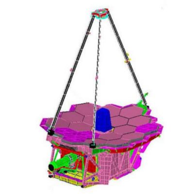
A system-level model of the James Webb Space Telescope in Ansys Thermal Desktop thermal-centric modeling software
When engineers want to include their software in their system model, they use a tool like the Ansys SCADE Suite model-based development environment for critical embedded software. This tool is a platform that platform engineers use to define and develop embedded control software, then run virtual hardware-in-the-loop simulations to test the algorithms.
For mission simulation, engineers use tools like Ansys Systems Tool Kit (STK) digital mission engineering software to conduct system-of-systems simulations of complex, interacting, independent systems. It includes real-world terrain, multiple physics, and powerful rendering. Similarly, process integration and design optimization tools, such as Ansys optiSLang process integration and design optimization software, enable engineers to automate system simulation workflows and intelligently explore their product’s design space in a single environment.
Related Resources
现在就开始行动吧!
如果您面临工程方面的挑战,我们的团队将随时为您提供帮助。我们拥有丰富的经验并秉持创新承诺,期待与您联系。让我们携手合作,将您的工程挑战转化为价值增长和成功的机遇。欢迎立即联系我们进行交流。