Synopsys and Ansys power the future of innovation—connecting silicon to systems.
TOPIC DETAILS
What is Aerodynamics?
Aerodynamics is the study of how air flows in and around objects and the forces generated by that interaction. It is a subset of gas dynamics focused on air, which in turn is a part of fluid dynamics, the science of how both gases and liquids behave. Air is a mixture of 78% nitrogen, 21% oxygen, and 1% other gases that make up Earth’s atmosphere. When air moves relative to an object, the pressure, density, and velocity of the air changes, and those changes result in forces on the object.
Scientists and engineers categorize those forces generated by flow around an object as either lift or drag. Drag forces are aligned with the flow direction, and lift forces are perpendicular to the flow direction. When designing systems with airflow, engineers work to create shapes that minimize unwanted aerodynamic forces and maximize those that enhance system performance.
A Brief History of Aerodynamics
Humans began inadvertently using aerodynamics on ships as early as the sixth millennium BCE with simple sails, and both Aristotle and Archimedes wrote about how air and water behaved. As civilization progressed, so did our use of aerodynamics to create inventions like Lateen sails and wind-powered machines for milling and pumping.
Things took a giant leap forward in the 18th century when Sir Isaac Newton applied the scientific method and mathematics to aerodynamics, developing the first theory of air resistance. Daniel Bernoulli defined the relation between pressure work and kinetic energy. Leonard Euler then expanded this in his Euler equations with a relation among flow pressure, velocity, and density — principles that led to our understanding of lift. With the addition of viscosity to the Euler equations, the Navier-Stokes equations were developed in the first half of the 19th century to accurately characterize fluid flow for most situations.
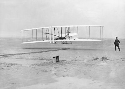
The most famous picture in aerodynamics shows the Wright Flyer during the first successful powered flight.
These scientific advances led to numerous improvements in wind power, sail design, and industrial applications. But the most transformative impact of aerodynamics was its application to heavier-than-air flight. Otto Lilienthal applied the science to gliders in 1891, and then the Wright Brothers demonstrated powered flight in 1903. The 20th century saw rapid advances in our understanding of the physics of aerodynamics, more accurate testing, and the application of computational fluid dynamics (CFD). These developments pushed aviation beyond the sound barrier in 1947, led to aerodynamic streamlining of other vehicles, enabled improvements in heating and cooling systems, powered the development of wind turbines, and made significant improvements in sports. Current aerodynamics research and its applications explore hypersonics and the use of improved computational methods and advances in high-performance computing to achieve even greater efficiency.
The Objectives of Aerodynamics
The primary objective of aerodynamics is to accurately predict the velocity, pressure, and density of the airflow around the object. Once those values are known, engineers can calculate the forces on the object, the heat transfer between the object and the air (if air temperatures are known), and any energy losses due to aerodynamic heating, viscosity, flow separation, shockwaves, and more.
The inputs and outputs from changes over time and the aerodynamic goals often conflict. The performance optimization of the design is a key goal in aerodynamic studies and is achieved by modifying the object’s shape while accounting for aspects, such as structural stresses or heat transfer. A good way to understand the objective of aerodynamics is to look at airfoils, which are used for the cross section of wings, sails, and propeller blades. An airfoil is defined as any streamlined body that produces more lift than drag. Lift is generated based on the airfoil shape and the angle of attack of the airfoil relative to the airflow.
A simplified way to describe lift is that velocity on one side of the foil is higher than the other, creating an air pressure drop on the low-pressure side and an air pressure increase on the high-pressure side. The difference in pressure between the sides creates the lift force (and also drag). Drag forces on an airfoil are counteracted by propulsion, and the goal of aerospace engineers is to minimize the amount of drag force.
Engineers who design airfoils and wings vary the shape to find the optimal geometry for the operating conditions of systems that require lift. Formulas, testing, and CFD are all used to design the optimal shape — for example, modifying the shape of a sail by adjusting the curvature and angle of the sail material or using movable surfaces on both the leading and trailing edges of aircraft wings to obtain the desired mix of lift and drag.
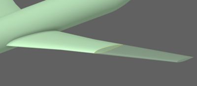
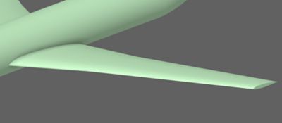
In this airfoil example, the transparency shows the contour of the airplane wing.
Aerodynamicists also focus on drag to improve the efficiency of systems moving through air. Automobiles are a prime example of how they use the principles of aerodynamics to streamline the car body, minimizing drag and thereby increasing fuel efficiency or battery range.
Beyond understanding and managing lift and/or drag, engineers use aerodynamics to control the boundary layer, the area where the velocity of flow varies from zero at the surface to the bulk velocity of the air. Further, the boundary layer’s velocity profile drives the heat transfer from the solid object to the air. Aerodynamics is also important for internal flow in heating or cooling systems, where engineers work to reduce losses in the ductwork and louvers to minimize the energy required to move air through the system.
Aerodynamics is also used to help engineers understand laminar flow, turbulent flow, and the transition from laminar to turbulent flow.
Common Applications of Aerodynamics
Any solid body that moves through air or that has air moving through it can benefit from aerodynamics. It becomes very important in high-speed applications because drag increases with the square of velocity. The aeronautics and automotive industries count on aerodynamics the most, but it touches many other industries. Here are some of the more common applications:
Aircraft
Aircraft design and operation are the largest and most significant applications of aerodynamics. Every aspect of fixed-wing and rotary-wing aircraft uses aerodynamics, and engineers need to understand the forces of flight — aerodynamic lift, drag forces, and thrust — that each part of a heavier-than-air vehicle produces. These forces combine around the center of mass to move the aircraft forward and rotate it around that center. This rotation is called “pitch” for up and down rotation, “roll” for rotation around the direction of travel, and “yaw” for rotation from side to side.
Here is a list of a few of the more common areas of focus for aircraft:
- Wings: Airplane wings come in all shapes and sizes. The airspeed of the aircraft, combined with the wing shape, generates an upward force — the lift. Wings support the entire aircraft while in flight, so aerodynamicists often collaborate with structural engineers to deal with steady, cyclical loads.
- Control Surfaces: Aircraft contain movable surfaces that use lift and drag to alter the forces exerted on an aircraft. The resulting moment about the center of mass changes the yaw, pitch, and roll of the aircraft and, consequently, the angle of attack and direction the aircraft is headed.
Control surfaces on wings consist of flaps and slats to change a wing’s shape, increase lift, and prevent stalling; spoilers to increase drag and slow the aircraft; and ailerons that move in opposite directions to control roll. These devices allow pilots to control the aircraft during flight, have optimal aerodynamics for takeoff and landing, and create minimum drag and sufficient lift during flight.
The control surfaces on the tail section include horizontal elevators that move in unison for pitch control and a vertical rudder that controls yaw.
- Fuselage: The body of an aircraft is called a fuselage, and engineers design the outside surface to minimize drag and, in some cases, to produce beneficial lift. The fuselage also contains the tail section, which has horizontal and vertical surfaces that stabilize the aircraft and support control surfaces.
- Propellers: Propellers are made of two or more blades, which are like wings, attached to a shaft rotating in the direction of travel. The lift produced by the blades creates thrust that propels the aircraft forward.
- Rotors: A propeller that produces thrust mostly against gravity is called a rotor. Rotating blades are attached to a shaft perpendicular to the direction of travel. Rotors are commonly found in helicopters and drones. Single-rotor applications also use the orientation of the blades as control surfaces that produce a moment about the center of gravity to direct the aircraft's motion. The same effect is accomplished in a multirotor application by varying the thrust produced by each rotor.
- Turbine Engines: Turbine or jet engines are propulsion devices that use internal flow past multiple stages of rotating blades, which leverage aerodynamic forces to perform work. The fan sections produce thrust, the compressor sections increase the pressure of the air to make combustion and propulsion more efficient, and the turbine sections extract energy from the exhaust to turn the fan and compressor sections. Static blades (stators) between the rotating stages (rotors) are shaped by leveraging aerodynamic principles to control the flow direction and optimize air compression or energy extraction from the fluid. The aerodynamics in turbine engines is very complicated and not only includes the design of the airfoil sections of the blades in rotating and static stages but looks at the internal flow through the engine, combustion, and the thrust produced by the high-speed exhaust. The same physics are also used in power turbines to generate shaft power, usually for electricity generation instead of propulsion.
- Sensors, Landing Gear, and Stores: Aircraft include myriad other subassemblies that interact with air. Any object that protrudes from the fuselage or a wing needs to take its aerodynamics into account, usually to minimize drag. Pitot tubes leverage aerodynamic laws to measure aircraft velocity based on pressure measurements.
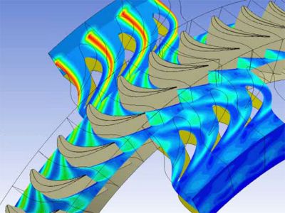
A computational fluid dynamics (CFD) simulation in Ansys CFX CFD software showing multistage flow in a gas turbine
Automotive Vehicles
The importance of aerodynamics in the design of transportation systems has increased as the speed of automobiles, motorcycles, trucks, and buses has increased. Engineers break down automotive aerodynamics into four areas:
- Drag: The strongest application of aerodynamics in the automotive industry centers around reducing drag on vehicles. One only needs to look at the shape over time to see how corners have been rounded, windshields have been tilted back, and trunks have been streamlined. On trucks, aerodynamic shells are added to cabs to gently direct air over the boxy cargo areas, and skirts keep air from being trapped underneath. Additionally, the industry uses wind tunnels and CFD early in the design process to adjust and modify the style of vehicles to increase gas mileage or range on electric vehicles.
- Downforce: High-performance vehicles, including race cars, use aerodynamics to create downward forces that keep the vehicle from losing traction as it turns. Designers usually add adjustable wings that are upside down so the lift they create pushes the car into the ground. More advanced vehicles shape the underside to create a lower-pressure zone that pulls the car down, increasing the downforce, and then expands toward the rear to reduce the vehicle drag.
- Internal Flow: The air moving around a vehicle is also diverted for cooling. The most common use is to flow air through a radiator to cool the engine, but ducting can also be used to cool brakes or bring fresh air into the cabin. Active shutters can make a great deal of balancing for vehicle aerodynamics at higher speeds and control the system’s cooling at lower speeds.
- Turbulence, Flow Separation, and Noise: Flow separation and the boundary layer of flow becoming turbulent create vortices referred to as eddies. The eddies produce noise, and the flow separation also increases drag. Engineers apply aerodynamic principles to minimize these effects, especially around protruding objects like mirrors and door handles.
Heating and Cooling (HVAC)
Aerodynamics also plays a role in the design of fans and ductwork used to move air, which control the temperature in buildings, vehicles, and electronics. Fans are constructed from rotating blades that increase the velocity and pressure of incoming air. Ducts and louvers are then installed to direct air and deliver it at a desired pressure and velocity.
HVAC engineers frequently pay attention to pressure rise, pressure drop, and airspeed in the systems they design, and they use aerodynamic principles to calculate those values over time.
Buildings, Bridges, and Other Built Structures
Civil and structural engineers work with aerodynamicists to understand and design for wind load on large civil structures. They calculate the forces on built structures of every size for normal wind levels and, in some parts of the world, for hurricane-, typhoon-, and tornado-level winds. Designers want to minimize damage and avoid failure. In high-rise structures, they also want to reduce building sway from wind loads. Dense urban areas face human-made wind funnels that concentrate and speed up winds.
The Tacoma Narrows Bridge failure is an example of aerodynamic loads exciting vibration in a structure to the point where the structure failed.
Bridges offer unique challenges because wind can interact with them, generating aerodynamic forces. Flexible bridges can sway wildly from wind loads if not designed properly, as was seen in the infamous Tacoma Narrows Bridge disaster. Another type of built structure impacted by aerodynamics is solar panel arrays. Wind loads can create significant forces on these flat panels, so engineers must design for these forces and predict when the panels need to be stowed in a safer position.
Sports
Aerodynamics also often plays a surprising role in sports. The most obvious application is the drag on runners and cyclists as they push through the air. World-class athletes move fast enough for drag to become a deciding factor in who wins and loses. Lift and turbulence also factor into any ball that travels at high speed or spins. The dimples on a golf ball and modern soccer balls or the hairs of tennis balls all contribute to triggering the boundary layer to become turbulent and delay flow separation. That allows the ball to go further or, with spin, change direction. Even golf clubs now include turbulators that generate vortices to control the air motion and increase the speed of the club.
Classifications and Equations Used in Aerodynamics
To get a better understanding of the aerodynamic behavior of a system, engineers and scientists define several aerodynamic conditions using pressure, density, and the velocity relative to the speed of sound.
Velocity Relative to the Speed of Sound
The speed of the air relative to the solid object impacts the physics that takes place when the air interacts with solid surfaces. If the object is moving faster than the speed of sound, the pressure wavefront that it produces cannot move away and the air becomes highly compressed, thereby forming a shock wave. Engineers convert the relative velocity into the Mach number, which is the ratio of the air velocity to the speed of sound to classify airflow:
- Subsonic: Air traveling below Mach 1. The airflow interacting with the object is subject to negligible to mild compression.
- Supersonic: Airflow moving above Mach 1. As the flow interacts with the object, shock waves can form.
- Transonic: As an object travels between ~Mach 0.8 and ~Mach 1.2, localized supersonic pockets can generate around it while it moves at subsonic speed and vice versa. This is because the local acceleration, or deceleration, of the flow can make it turn to supersonic or subsonic.
- Hypersonic: When an object’s velocity is greater than Mach 5.0, enough heat is generated by the shock waves to cause chemical reactions in the air. This type of flow is so complex that a special category in the supersonic flows was created.
Pressure/Density
Air is considered a compressible fluid. As pressure increases, the density also increases, and the opposite is also true. However, at low speeds (Mach <0.3), the density change is small enough to be negligible and it is safe to assume that the density remains constant. This type of flow is classified as incompressible flow, and it is easier to approximate.
At higher speeds, the density change is larger than 5% and cannot be neglected anymore as air passes around a fixed object. This type of flow is called compressible flow.
Common Aerodynamic Equations
Multiple volumes of textbooks lay out the equations used to describe the quantities that aerodynamicists care about as air flows around and through solid objects. Here is a list of the most common:
Ideal Gas Law
The Ideal Gas Law defines the relationship among pressure, volume, and temperature. It is used in aerodynamics to calculate the interaction of those three values.
$$PV = nRT$$
Where:
P is the pressure of the gas.
V is the volume occupied by the gas.
n is the number of moles of the gas (the amount of substance).
R is the ideal gas constant, a physical constant that relates the energy scale to the temperature scale. Its value depends on the units used for the other variables.
T is the temperature of the gas, measured on an absolute scale (in Kelvin).
Bernoulli’s Principle
The Bernoulli equation states that energy is conserved and the sum of the pressure, kinetic, and potential energies remains constant. For most aerodynamic flow, the height of the fluid doesn’t change, so the third term is constant. Therefore, the equation defines the key relationship of pressure changing with the square of velocity. So if velocity increases, then pressure decreases, and that is the concept that engineers leverage to shape airplane wings to create lift.
The Bernoulli equation is:
\[ P + \frac{1}{2}\rho v^2 + \rho g h = \text{constant} \]
Where:
P is the static pressure of the fluid at the point.
ρ (rho) is the density of the fluid.
V is the velocity of the fluid flow.
g is the acceleration due to gravity.
h is the height of the fluid above a reference point.
Coefficient of Drag and Lift
The drag coefficient (CD) and the lift coefficient (CL) are dimensionless, and they define the force acting on an object in a fluid environment. They are defined as:
$$C_D = \frac{2F_D}{\rho V^2 A}$$
$$C_L = \frac{F_L}{\frac{1}{2}\rho V^2 A}$$
Where:
FD is the drag force.
FL is the lift force.
ρ (rho) is the mass density of the fluid.
V is the flow velocity relative to the object.
Navier-Stokes
The Navier-Stokes equations fully define fluid dynamics for gases and liquids. There is no closed-form solution for these equations, so numerical methods are used to solve for real-world applications. The equations are:
Continuity:
$$\nabla \cdot \vec V = 0 $$
Momentum:
$$ \rho \left[ \frac{\partial u}{\partial t} + \nabla \cdot ( \vec Vu)\right]= - \frac{\partial p}{\partial x} + \mu \nabla ^{2} u + F_{b,x} $$
$$ \rho \left[ \frac{\partial v}{\partial t} + \nabla \cdot ( \vec Vv)\right]= - \frac{\partial p}{\partial y} + \mu \nabla ^{2} v + F_{b,y}$$
$$ \rho \left[ \frac{\partial w}{\partial t} + \nabla \cdot ( \vec Vw)\right]= - \frac{\partial p}{\partial z} + \mu \nabla ^{2} w + F_{b,z} $$
Energy:
$$ \rho C_p \left[ \frac{ \partial T }{\partial t} + \nabla \cdot \left( \vec V T \right) \right] = k \nabla ^2 T + \left(\overline{\overline{\tau}} \cdot \nabla \right) \vec V + \dot S_g $$
Where:
ρ (rho) is the density of the fluid.
t is time.
V is the freestream velocity.
f is the body force.
T is the tensor of the surface forces (pressure and viscous).
k is the heat conduction.
q is the heat production.
Understanding and Optimizing Aerodynamics With Simulation
Fluid dynamics is a difficult discipline because measuring fluid behavior in the real world is complicated and expensive, and most applications don’t lend themselves to simple equations. In the early days of aeronautical engineering, organizations like NASA conducted detailed testing for a large number of shapes and generated tables that engineers could use for their own designs. Then, in the 1960s, advances in computing and numerical methods made CFD a practical tool that could be used for arbitrary geometry to solve the Navier-Stokes equations and accurately predict pressure, velocity, temperature, turbulence, and the forces on solid objects as air flowed around or through them.
Most CFD simulations fall into one or more of the following four categories.
External Flow CFD
This is the most common type of simulation that engineers use. They may begin early in the design process with a fast, GPU-based solver, such as the one found in Ansys Discovery 3D product simulation software. This type of preliminary exploration tool allows teams to try out changes to geometry and boundary conditions, conducting what-if studies and narrowing down their design.
As the design matures, they can apply full CFD tools, such as Ansys CFX computational fluid dynamics software and Ansys Fluent fluid simulation software, to gain a more accurate understanding of the aerodynamic performance of their system. Engineers can also use a gradient-based optimization method like the adjoint solver found in Fluent software to automatically determine optimal geometry shapes to achieve their design goals. From fuselages to turbine blade designs, properly deployed CFD can drastically improve the time to market for even the most challenging aerodynamic situations.
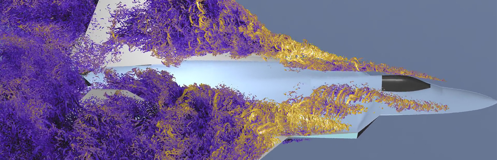
An example of turbulence simulation for an advanced fighter design, predicting how the vortices upstream impact the control surface further back on the aircraft
Internal Flow CFD
Internal flow can use the same CFD tools as external flow CFD, with the main difference being that the air volume is surrounded by solid objects instead of moving around them. In some situations, engineers can also use tools like Ansys Thermal Desktop thermal-centric modeling software to create one-dimensional network flow models where ducts, vents, and fans are simplified into simple equations and the exact geometry does not need to be converted into a discrete mesh. This can be much more efficient for larger internal flow networks.
Conjugate Heat Transfer
Most aerodynamic simulations are used to calculate forces on solid objects. But heat transfer is another application where numerical methods can quickly give accurate estimates of how heat flows between an object and the air moving past it — referred to as conjugate heat transfer. This bidirectional multiphysics application is a fundamental part of the design of forced-air electronic cooling systems, many heat exchangers like automotive radiators, and cooling applications in high-temperature energy and propulsion systems like turbine engines. Many CFD tools like Fluent software have conjugate heat transfer capabilities built in. Specialty tools like Ansys Icepak electronics cooling simulation software can be used for electronics cooling, or CFD tools can be coupled to finite element packages like Ansys Mechanical structural finite element analysis software to predict thermal stresses. Heat transfer can also be simulated using system-level tools like Thermal Desktop software.
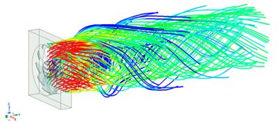
An Ansys Icepak electronics cooling simulation software simulation of a cooling fan
Fluid-Structure Interaction
Fluid-structure interaction (FSI) is another type of multiphysics simulation used for aerodynamics. It comes into play when the forces generated from aerodynamic loads cause the shape of the object they are pushing on to change, which then causes changes to the flow. Helicopter blades, propellers, and wind turbine blades are good examples of systems where FSI should be used to understand this interaction and design around potential damage. In certain situations, aero loads can cause resonant vibration in the structure, a situation referred to as flutter.