ANSYS BLOG
July 13, 2022
Thermal Cycling Failure in Electronics
Each time a device is turned off and on, its temperature changes. (Just think about how often your phone lights up all day.) Energy flowing through several layers of tightly stacked materials causes devices to heat up, then rapidly cool down. This repeated oscillation between temperatures over the lifetime of a device is called thermal cycling.
Why Thermal Management is Important
Thermal cycling, the process of a device moving through hot and cold states, is one of the biggest areas that causes failure in electronics. If thermal fatigue occurs, multiple systems within the devices can be affected, resulting in warpage, solder weakness, breaking or cracking — and eventually, if left unmitigated, overall product failure.
Because electronics are in everything today, the strain caused by thermal cycling affects components in devices across industries such as:
- Automotive
- Aerospace and defense
- Biomedical
- Manufacturing
- Consumer goods

Figure 1: Causes of electronics failure.
What Makes Components Sensitive to Thermal Cycling?
There are several reasons why components can be sensitive to thermal cycling, including where a component is placed on a circuit board and the type of component, such as quad-flat no-lead (QFN) packages, ball grid arrays (BGAs), and ceramic capacitors. These components do not have compliant leads, and therefore only the solder is available to absorb the strain.
With strain-sensitive components, it is important not to place them in high-strain areas on the board, such as:
- Near mounting holes
- Areas between or near larger stiff components (like inductors)
- Near V-scored board edges, where breaking of the V-score may damage the part
QFN Placement Example
In Figure 2, a QFN has been placed between two large inductors on a printed circuit board (PCB) with four corner standoffs. During a thermal cycling event, you can see the high-strain areas (indicated by red and yellow) that develop. Placement of the QFN in the resulting high-strain area could lead to solder joint failure of the QFN.

Figure 2: A quad-flat no-lead (QFN) package placed between two inductors on a printed circuit board (PCB) undergoing thermal analysis.
Solder Strain in Electronics
Soldering is one of the most basic ways to attach components on a circuit board. Like a metal hot glue, solder is melted and used to stick pieces together as it hardens. While solder degradation can be caused by vibration or shock, thermal cycling is most commonly the reason for solder joint failure.
Every material has a unique coefficient of thermal expansion (CTE), and mismatches between material CTEs is a major driver of solder fatigue. When solder is strained, the bonds between your components and the circuit board can deform, crack, or break, leading to failure risk.

Figure 3: Ball grid array (BGA) ball with a thermal fatigue crack.
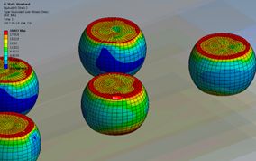
Figure 4: Stresses in BGA balls due to thermal-mechanical loading.
Read our Top 5 Reasons for Solder Joint Failure blog to learn more.
Accelerating Thermal Cycling Life Testing
Everything on a circuit board is not purely electrical. Often the layered materials used to relay electricity are buried deep within the circuit board and cannot be observed from the top or bottom. As electricity passes through them, they grow, shrink, and deform. Predicting how these components will react to thermal cycling is critical for accurate life testing.
Ideally, to prevent failure caused by thermal fatigue, engineers should reduce thermal stressors in the design stage. Using simulation, they can see where stress will occur and make changes to the number of material layers and restraints, location of components, and material underfill before a physical prototype is made.
When using simulation to test thermo-mechanical reliability risks, it is important to use software that has finite element analysis (FEA) or structural analysis capabilities. FEA is a mathematical representation of a physical system that uses meshing to map elements onto your model. The meshing technique is incredibly important for an accurate analysis.
Designing Electronics That Last
Understanding thermo-mechanical reliability risks is a critical step when designing electronic devices. Temperature cycling is one of the main causes of electronics failure, and not designing devices with this risk in mind can result in unexpected product failure in the field. Using simulation is an important first step engineers can take to eliminate lengthy design cycles and reduce multiple prototype iterations.
Learn more about component level reliability, board level reliability, and system-level interactions that affect reliability by viewing this on-demand webinar: How to Predict Thermal Cycle Failures of Electronics