Synopsys and Ansys power the future of innovation—connecting silicon to systems.
Ansys Blog
January 25, 2019
How Simulation Changed the Rocket Engine Design Cycle
The U.S. Air Force started the Upper Stage Engine Technology (USET) program to develop an affordable replacement for the RL10 hydrogen rocket engine.
Development and production of the RL10, as well as other historical rocket engines, required large development teams with substantial labor costs and extensive test programs.
USET aimed to offset this costly process with new rocket development methods that included physics-based modeling and simulation.
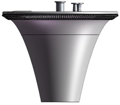
The DESLA engine
(image courtesy of P3 Technologies)
This program would eventually lead to the development of P3 Technologies’ dual-expander, short-length aerospike (DESLA) engine.
At the start of the USET program, rocket development was typically based on empirical data. The challenge was that empirical data had limited value when applied to new technologies and propellants.
“We found that Ansys simulation technology had the capabilities to simulate how our engines would run,” said Philip Pelfrey, president of P3 Technologies. “Since these simulations were physics-based, we could model the engine to run on any fuel at any size, speed or pressure.”
As an Ansys Startup Program member, P3 Technologies continues to use simulation to redefine its development cycle and optimize its DESLA engine.
Optimizing the Heat Transfer in a Rocket Engine with Simulation
Every second that the DESLA rocket engine fires is a heat transfer balancing act. Since liquid hydrogen is cryogenically cold, it acts as both the fuel and coolant to the engine.
Before the fluid burns, it first cools the engine’s nozzle. If the nozzle gets too hot, then it can fail — or even melt.
As the fuel heats up, it quickly becomes a high-pressure gas. This heat is used to turn the engine’s turbine before the gas goes into the combustion chamber. If the fuel doesn’t pick up enough heat, the turbine will not have sufficient power for the cycle.
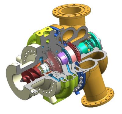
The performance of the DESLA
turbo pump assembly (TPA) relies
on optimizing heat transfer
(image courtesy of P3 Technologies)
“Ansys helps us to balance the heat cycle to maximize the engine output without damaging the nozzle,” said Pelfrey. “The simulations help us size passages to optimize the flow, pressure loss and heat transfer throughout the system.”
Without simulation, P3 Technologies’ design cycle would include a lot of manual iterations. By optimizing the flow digitally, P3 Technologies will reach a final design faster and on a smaller budget.
Simulation Differentiates a Rocket Engine’s As-manufactured and Operating Geometries
Believe it or not, the as-manufactured geometry of a DESLA rocket doesn’t match the operating geometry.
“When the engine is running, parts are spinning at thousands of rotations per minute (RPM) with large thermal gradients and extreme pressure,” said Pelfrey. “All of these loads will make parts shrink, expand, twist and bend.
“You want parts to operate at their optimal geometry, but these loads ensure that the optimal geometry and as-machined geometry are very different.”

Test of the modular thrust chamber.
The as-manufactured geometry and
operational geometry of the DESLA
turbopump are not the same
(image courtesy of P3 Technologies)
Assessing how parts change from their as-manufactured geometry to their operating geometry is a complex process. Pelfrey notes that without simulation, the design cycle of these parts would include a lot of iteration.
“However, within Ansys CFX, we can add the pressure, thermal and centripetal loads to our geometry. From there, we can backout what the as-manufactured geometry needs to be,” explained Pelfrey. “This way we can ensure the parts are machined properly and that they will have their optimal shapes during operation.”
To gain access to simulation tools that can optimize a product’s shape and cooling systems, become a member of the Ansys Startup Program.