Synopsys and Ansys power the future of innovation—connecting silicon to systems.
-
-
Software gratuito per studenti
Ansys potenzia la nuova generazione di ingegneri
Gli studenti hanno accesso gratuito a software di simulazione di livello mondiale.
-
Connettiti subito con Ansys!
Progetta il tuo futuro
Connettiti a Ansys per scoprire come la simulazione può potenziare la tua prossima innovazione.
Customer Center
Supporto
Partner Community
Contatta l'ufficio vendite
Per Stati Uniti e Canada
Accedi
Prove Gratuite
Prodotti & Servizi
Scopri
Chi Siamo
Back
Prodotti & Servizi
Back
Scopri
Ansys potenzia la nuova generazione di ingegneri
Gli studenti hanno accesso gratuito a software di simulazione di livello mondiale.
Back
Chi Siamo
Progetta il tuo futuro
Connettiti a Ansys per scoprire come la simulazione può potenziare la tua prossima innovazione.
Customer Center
Supporto
Partner Community
Contatta l'ufficio vendite
Per Stati Uniti e Canada
Accedi
Prove Gratuite

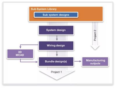
The top-down methodology of Ansys SaberES Designer makes it a powerful tool for synthesis automation of system integration. It uses a database-driven design flow, which is supported by pre-defined part sets from corporate-wide libraries. These libraries cater to various design types such as sub-system design, system design, wiring design, and bundle design. The integration of these designs into a single electric system design database is key to ensuring a robust and accurate system integration.
Top-Down Design Flow
The top-down methodology employed in SaberES Designer for synthesis automation of system integration provides a platform for design and automation verification. SaberES Designer is a database driven design flow where corporate-wide libraries provide predefined part sets for the following design types:
- Sub-system design: Reusable schematics with logical connections that represent a function, such as external lights, braking, and engine control.
- System design: A vehicle projects sub-system designs are selected and used to build and synthesize the system design.
- Wiring design: Generated from the system design and evolved by assigning physical objects such as wires, shells, inline connectors, and more.
- Bundle design: Generates 2D production harness drawings.
Having one electric system design database ensures system integration will be correct and robust for fast, accurate releases.
Sub-System Design
Sub-system designs (SSD) are reusable schematics with logical connections that represent a function, such as external lights, braking, and engine control. SSD are created based on the specifications determined by the function and stored in sub-system libraries.
- Electric components are placed from the libraries that also can contain a hardware model to be used to simulate the function.
- Connectivity is created and defined using signals from the database.
System Design
SSD are used to build and synthesize the system design for a series of vehicle projects including excluding functions. System design is not about adding data, but about the integration of functions.
- Data network topologies are created and can be evaluated.
- Electrical options are configured for the complete project.
Wiring Design
The wiring schematic design is generated from the system design by adding the excluding options like LHD and RHD. Users can assign physical objects from a corporate database including wires, shells, inline connectors, and more. Using SaberES Designer’s Connector Manager Viewer, users can partition a design into harnesses and quickly ensure correct inline cavity assignments across the complete vehicle. The Assembly Library can be used to build filters for each unique buildable product with the Assembly Library.
- Your physical wiring system can now be simulated to optimize it against the requirement to stay away from over engineering using pre-defined test benches.
- Connections with the 3D mechanical computer aided design (MCAD) tools, such asCatia, Creo, and NX, will get BoM filtered for each vehicle configuration.
Bundle Design
A top-down design flow generates the harness drawing using data from the previous level. SaberES Designer wiring design is ideal for electrical objects and connectivity in Bundle Design.
- MCAD files containing the 3D routing can be imported and used to automate the creation of the harness drawings.
- Multiple formats are supported to export your harness data to manufacturing that can be used to create formboards, cut and crimp data, and more.
The journey through the process of electrical system design, wiring, and harness using SaberES Designer software reveals the effectiveness of the top-down methodology. Each step, from the creation of sub-system designs to the synthesis of system design, and the assignment of physical objects in wiring design, contributes to the creation of an efficient electrical system. The final stage, bundle design, completes the process by generating 2D production harness drawings. The result is a comprehensive, optimized, and efficient electrical system, integral to the smooth operation of vehicle projects.
Learn more about how Ansys SaberES Designer software can help with your electrical designs.


The Advantage Blog
The Ansys Advantage blog, featuring contributions from Ansys and other technology experts, keeps you updated on how Ansys simulation is powering innovation that drives human advancement.