ANSYS BLOG
September 17, 2020
How to Improve Compressor Efficiency with Design Optimization
Positive displacement compressors work by drawing in a gas and increasing its pressure by forcing it into a smaller volume. The force is applied by moving parts that displace the gas through the compression chamber.
There are many different types of positive displacement compressors, such as piston, screw and scroll compressors, as well as rotary lobe compressors. They can be applied to applications in heating, ventilation and air conditioning (HVAC), refrigeration systems, industrial compressed air supplies and more.
Designers of positive displacement compressors can use simulation to balance performance, efficiency and reliability while, avoiding unwanted noise and vibration.
Use Simulation to Improve Compressor Efficiency
Minimizing leakage losses at the discharge phase of the compression cycle is a key to compressor efficiency. As the gas is compressed into the smaller volume, it eventually reaches the point where it will be discharged into a larger volume. The discharge flow is complex and is not easily calculated by empirical methods.
Compressor designers often begin with 1D and 2D methods to size the compressor and obtain preliminary aerothermal performance data based on fundamental principles and empirical data. A range of 3D computational fluid dynamics (CFD) simulations are typically performed to optimize the design.
Early in the design process, designers want to know if geometry changes will improve compressor performance. As the design evolves, higher fidelity CFD simulations with more advanced physical models can more accurately represent what they can expect to see in a physical test.
Ansys Forte for Upfront Design Analysis
Because compressors have moving geometries with microns of clearances, mesh generation can be difficult and time consuming. Ansys has several partner solutions for mesh generation, such as PDM Analysis and TwinMesh. However, if you’re looking to add a quick and easy solution early in the design process, consider Ansys Forte.
Forte reduces the CFD solve time by eliminating the pre-processing step. It also introduces models for gap flows so that the mesh in these areas does not need excessive refinement.
Compressor Design Optimization Workflow
Forte has a streamlined workflow that accelerates the time to reach an optimal design idea. This workflow is 3X to 10X faster than what is being used by some of the industry leading compressor manufacturers.
The workflow starts by creating a geometry in Ansys SpaceClaim and exporting it as a surface mesh. This is then imported into Forte where a workflow tree simplifies the setup. Forte uses automated meshing to speed up the simulation.
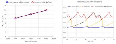
The mesh is created on the fly and adaptively refines based on the solution and geometry. Built-in features help handle gaps that compressors usually have. To accurately predict flow rates in Forte, gap flows must be predicted to simulate leakage. Forte’s built-in gap models yield accurate results within 5%.
Left: Comparison to experimental data for mass flow rate vs. RPM.
Right: Comparison of local pressures to measured pressure vs. time.*
After using Ansys Forte to improve the design early in the design phase, you can take the geometry and move into Ansys CFX or Ansys Fluent to include more physical details, such as detailed gap flows, multiphase simulations for oil-flooded compressors and more real gas modeling options to produce high-fidelity simulations before prototyping and testing.
*Data from City University of London:
Rane, S., Kovačević, A. (2017). Algebraic generation of single domain computational grid for twin screw machines. Part I. Implementation, Advances in Engineering Software, 107, pp. 38-50.
Kovačević, A, Rane S. (2017). Algebraic generation of single domain computational grid for twin screw machines Part II – Validation, Advances in Engineering Software, 109, pp. 31-43.
