ANSYS ADVANTAGE MAGAZINE
DATE: 2018
Qualifying Additive Manufactured Rocket Parts with Simulation
By Dieter Hummel, Thermomechanics Engineer, ArianeGroup GmbH, Ottobrunn, Germany and Roger Schlegel, Director of Consulting Dynardo GmbH, Weimar, Germany
As the aerospace industry moves to implement additive manufacturing, it must validate that components will survive in an environment where a single failure in a launch vehicle could force termination of a mission. When introducing a new production technology, because many parts must be produced and verified until target quality can be achieved, the traditional trial-and-error validation process is very time-consuming and expensive. ArianeGroup used Ansys and Dynardo simulation software to create a simulation-based workflow that predicts part quality and has the potential to significantly reduce the process time required by the traditional method.
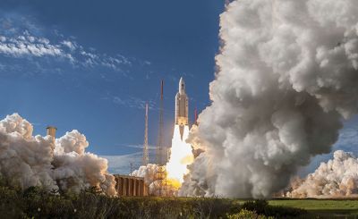
Avoiding mission failure is the number one requirement for a launch vehicle. Each failure sacrifices the launch cost of about $150 million and the loss of a satellite that might cost hundreds of millions of dollars and take years to rebuild. Between April 2003 and December 2017, ArianeGroup’s Ariane 5 heavy-lift launch vehicle successfully delivered 82 consecutive payloads into geostationary transfer orbit (GTO) or low Earth orbit (LEO) without a single failure. ArianeGroup is currently developing the next-generation Ariane 6 launch vehicle with similar performance to the Ariane 5 but with lower manufacturing costs and launch prices. Metal additive manufacturing is being used in the Ariane 6 to reduce manufacturing cost and lead time, and to decrease part weight and the space required to accommodate it.
In the company’s liquid propulsion engineering cluster, one department focuses on combustion devices, a generic name for all engine components that handle hot gases, such as gas generators, power units and main thrust combustion chambers. ArianeGroup qualified the first parts for additive manufacturing using an expensive trial-and-error process that involved building prototypes and testing them to determine their performance. The thermomechanics team within the combustion device department has recently developed an automated workflow using Ansys Mechanical to simulate the additive manufacturing process. During the development process for new components, engineers identify risks during the printing process by leveraging simulation to predict temperature, stress and strain evolution. Ansys optiSLang allows the team to automate the process and calibrate the model to optimize manufacturing process parameters at a fraction of the cost of the current hardware trial-and-error method.
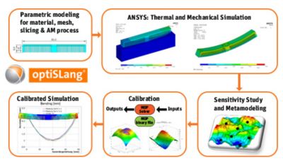
Workflow uses ANSYS Mechanical and ANSYS optiSLang to calibrate simulation models.
PREVIOUS VALIDATION PROCESS
The powder bed metal additive manufacturing process works by placing a thin layer of metal powder on a build plate. A laser sweeps the build plate to selectively melt tiny sections of the powder to form one layer of the part. As each section cools it contracts, but the solid underlying layers resist these contractions, generating residual stresses. These residual stresses can generate distortions in the finished part (plastic strain), and, in the worst case, cracks that often cannot be detected with inspection because they are hidden by other sections of the part. Combustion devices are critical to the success of the mission, so switching to a new manufacturing process requires proving that the new process is free of cracks and other defects.
Before approving additive manufacturing parts for inclusion in the Ariane 6, ArianeGroup engineers must understand the process, determine the effects of key process parameters on part quality, and develop a manufacturing process that reliably allows them to meet final quality requirements including the variability of each process parameter.
SIMULATING THE ADDITIVE MANUFACTURING PROCESS
To develop a workflow to increase the speed and reduce the cost of validation, ArianeGroup and Dynardo engineers first created a model of a relatively simple part. They simulated the additive manufacturing process with Ansys Mechanical finite element analysis software and developed an Ansys Parametric Design Language (APDL) script that mimics the metal additive manufacturing process by slicing the entire structure into individual layers. The elements of the printed layer are then activated with the EALIVE command, which sets their temperature at the melting temperature of the material used to produce the part. Different variations of this script either activate the entire layer at once, activate rectangular elements on a layer in a step-wise fashion, or sequentially activate angular swathes across the layer. The elements are then allowed to naturally cool, and the residual stresses are tracked in each element. Another layer of elements is then activated in the model in the same way as the preceding layer. The script simulates the complete process of building the part and tracks the residual stresses and deformation of each element.
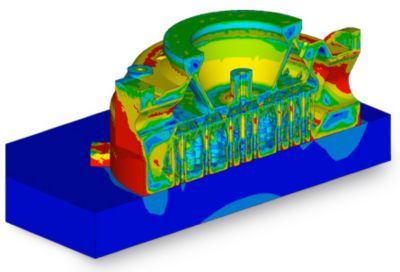
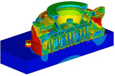
Finite element model of the injector
Recently, Ansys has released Ansys Additive Suite, which reduces the need for APDL script development by users, supports the parameterization of the models and optimizes solver settings.
CALIBRATING THE SIMULATION MODEL
To prove the quality of the simulation model, test structures were produced and the model calibrated to measured deformation and residual stresses. In the calibration process, the variation space of the material parameter, the process parameter and the discretization parameter is scanned by a design of experiment (DoE). From this, a metamodel of optimal prognosis (MOP) is generated by optiSLang. This metamodel shows how process variability affects the results. The MOP is then used to calibrate the simulation model parameters to match the results of physical measurements on the part. Important parameters used in the calibration were the element size on the x, y and z axes, the laser path (activating a complete layer, one rectangular element at a time of various sizes, or an angular swatch across the layer), the time until melting of the next partial layer and the time until placement of the next powder layer.
Measurement of the manufactured material revealed anisotropic deformation and strength behavior, so engineers used Dynardo’s multiPlas, a custom anisotropic multisurface elastoplastic material model in Ansys Mechanical, to match this anisotropic behavior, and incorporated it into the additive manufacturing model. Comparing isotropic and anisotropic elastoplastic material models, the team determined that the lower yield and ultimate strength in the normal direction (between 80 percent and 90 percent of the strength in the in-plane direction) has a very important effect on the evolution of plastic strains. Employing this anisotropic material model, the finite element model was calibrated to predict the physical build to a high level of accuracy.
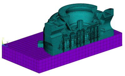
Once the process parameter at the test structure was calibrated, the simulation workflow was ready to forecast deformation, stresses and cracks of the part to be qualified. ArianeGroup and Dynardo engineers simulated the process of building a more complex part, an injector for a development prototype. The finite element model had 1,065,000 nodes and 620,000 quadratic volume elements. It required 7 hours for thermal analysis and 32 hours for mechanical analysis on a personal computer with 4 central processing units. The forecast using anisotropic material models was an excellent match to the measurements of the printed injector.
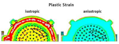
Comparison between isotropic and anisotropic elastoplastic material models. Anisotropy has a major impact on plastic strain forecast.
OPTIMIZING THE PART GEOMETRY AND MANUFACTURING PROCESS
Next, engineers extended the workflow to investigate the effect of part geometry variation and key additive manufacturing process parameter variations on residual stress, plastic strain and distortion of the finished part. They created a fully automated workflow that identifies the sensitivity of part quality to each design and process parameter incorporated into the DoE used to build the MOP. The workflow can optimize the part geometry and the additive manufacturing process at the same time.
The exceptionally high cost of a failure in the extremely competitive aerospace industry makes it essential to perform a thorough validation process before adopting new technologies. In the past, this has meant a long trial-and-error process to validate new manufacturing processes. Simulation can be combined with a much smaller volume of physical testing to provide fast qualification and insertion of new technologies without sacrificing mission safety. For example, this new workflow drastically reduces the time required to validate a new part, potentially making it possible to optimize the part geometry and additive manufacturing process with only two builds, one to validate the simulation model and the second to validate the optimized part design and process.
ArianeGroup engineers are planning to use this process to reduce the time and cost required to validate parts for the new Ariane 6 launch vehicle.
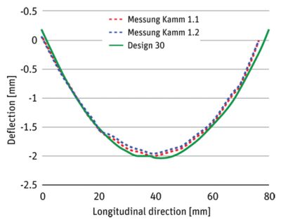
Deformation predicted by calibrated simulation model closely matches physical measurements.
Von Mises stresses
Displacement
现在就开始行动吧!
如果您面临工程方面的挑战,我们的团队将随时为您提供帮助。我们拥有丰富的经验并秉持创新承诺,期待与您联系。让我们携手合作,将您的工程挑战转化为价值增长和成功的机遇。欢迎立即联系我们进行交流。