Synopsys and Ansys power the future of innovation—connecting silicon to systems.
-
-
Software gratuito per studenti
Ansys potenzia la nuova generazione di ingegneri
Gli studenti hanno accesso gratuito a software di simulazione di livello mondiale.
-
Connettiti subito con Ansys!
Progetta il tuo futuro
Connettiti a Ansys per scoprire come la simulazione può potenziare la tua prossima innovazione.
Customer Center
Supporto
Partner Community
Contatta l'ufficio vendite
Per Stati Uniti e Canada
Accedi
Prove Gratuite
Prodotti & Servizi
Scopri
Chi Siamo
Back
Prodotti & Servizi
Back
Scopri
Ansys potenzia la nuova generazione di ingegneri
Gli studenti hanno accesso gratuito a software di simulazione di livello mondiale.
Back
Chi Siamo
Progetta il tuo futuro
Connettiti a Ansys per scoprire come la simulazione può potenziare la tua prossima innovazione.
Customer Center
Supporto
Partner Community
Contatta l'ufficio vendite
Per Stati Uniti e Canada
Accedi
Prove Gratuite
DETTAGLI DELL'ARGOMENTO
Cos'è il beamforming?
Il beamforming è il processo di formazione e indirizzamento di un fascio elettromagnetico ― come segnale wireless ― per creare diversità spaziale per un'antenna. Il beamforming consiste nel creare e controllare un fascio in un sistema antenna-ricevitore e nell'indirizzare l'energia ai ricevitori in una direzione specifica, impedendo al tempo stesso all'energia di dirigersi altrove.
Senza beamforming, i segnali elettromagnetici, come le onde a radiofrequenza, si diffonderebbero in tutte le direzioni dal trasmettitore senza alcun grado di controllo. Ciò comporterebbe una minore precisione e un basso rapporto segnale-rumore nel ricevitore previsto.
Il beamforming è strettamente correlato al beam steering. Sebbene i due termini siano spesso utilizzati in modo intercambiabile, il beamforming crea un fascio simile a una matita e lo spinge in una direzione specifica, mentre il beam steering aggiorna continuamente le caratteristiche del fascio per seguire un dispositivo ricevente e adattarsi ai cambiamenti dell’ambiente.
Come funziona il beamforming?
Il beamforming controlla la fase e l'ampiezza di più sorgenti di segnale all’interno di un array di antenne per creare un singolo fascio concentrato o più fasci simultanei.
La fase e l'ampiezza vengono applicate a livello di ciascun flusso di segnale, che potrebbe trovarsi nella singola antenna o nel punto in cui più antenne si combinano per formare array secondari.
Per dirigere i fasci, i segnali che si irradiano dalle sorgenti di segnale indipendenti (antenne) sono impostati in modo da sovrapporre la loro energia irradiata nella direzione desiderata, creando dei nulli in altre direzioni. I nulli si sviluppano nelle direzioni in cui viene irradiata una quantità minima di energia e rappresentano le direzioni in cui gli array riceventi hanno una sensibilità pari quasi a zero.
Sono disponibili tre elementi principali per la formazione e l'indirizzamento di un fascio:
- Elaborazione spaziale del segnale: Analizza le caratteristiche spaziali e le fasi relative di un segnale iniziale.
- Adattamento del segnale: Regola dinamicamente il guadagno e la fase di ciascuna antenna in base all'analisi iniziale.
- Combinazione dei segnali: I segnali provenienti da ciascun elemento dell'antenna vengono combinati per creare un fascio focalizzato diretto verso il ricevitore. In questa fase è anche possibile annullare le interferenze in altre direzioni.
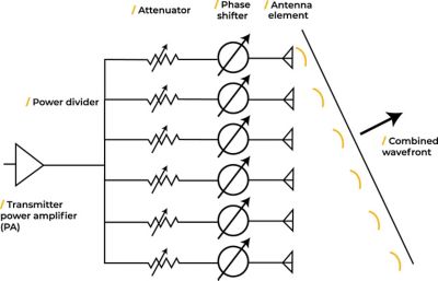
Schema del circuito di un array a fasi
Poiché i trasmettitori e i ricevitori funzionano in modo combinato, anche i ricevitori svolgono un ruolo nella modalità e nel momento in cui i segnali vengono ricevuti. I ricevitori possono essere utilizzati per controllare il modello di sensibilità del sistema di antenne ritardando i singoli segnali che arrivano a ciascuna antenna dell'array. Il controllo del ritardo del segnale coincide con il controllo della sua fase perché la fase nel dominio della frequenza è analoga al ritardo nel dominio del tempo. Il controllo del ritardo/fase consente di modificare i fronti d'onda nella direzione desiderata e di ottimizzarne la combinazione.
Inoltre, la manipolazione dell'ampiezza del segnale ricevuto consente di controllare ciascun elemento dell'antenna (forte o debole) per ottenere il segnale massimo possibile nelle direzioni di interesse, sopprimendo i lobi secondari del modello dell'array per ridurre l'energia erogata in direzioni non volute. In questo modo si migliora la forza e la qualità del segnale nella direzione desiderata, riducendo al contempo il segnale nelle direzioni che non sono di interesse. Ciò riduce la possibilità che un array interferisca con altri sistemi RF in modalità di trasmissione e riduce la sua sensibilità ad altre potenziali fonti di interferenza provenienti da direzioni diverse rispetto alla sorgente del segnale desiderato. Questo aspetto è molto importante nelle configurazioni di array a fasi di grandi dimensioni con un gran numero di antenne in cui vengono utilizzati più fasci per monitorare e gestire più utenti wireless e sistemi di comunicazione.
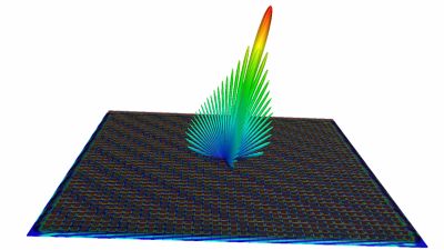
Antenna di array a fasi di grandi dimensioni con una rappresentazione grafica del modello di radiazione dell'antenna calcolata dal software di simulazione elettromagnetica ad alta frequenza Ansys HFSS. La codifica a colori e l'altezza del beamforming sopra il piano dell'antenna mostrano la potenza del segnale in funzione della direzione. La direzione del segnale di picco e i lobi laterali della radiazione secondaria sono chiaramente visibili.
Tecnologie di beamforming
Per generare, controllare e dirigere un fascio di energia focalizzato vengono utilizzate diverse tecniche di beamforming.
Beamforming a banda stretta
Il beamforming a banda stretta è una delle tecnologie più semplici. Utilizza una frequenza singola molto specifica che fornisce un fascio ben definito che si presume sia lo stesso per tutti gli elementi dell'antenna alla frequenza centrale. Viene comunemente utilizzato nella tecnologia sonar e nei sistemi di comunicazione a banda stretta.
Beamforming a banda larga
Il beamforming a banda larga è più difficile da controllare perché la frequenza si trova su una banda molto più ampia, in cui un unico valore di sfasamento finirebbe per sfocare il fascio del segnale. Il segnale nell'antenna deve essere regolato in base alla larghezza di banda tramite la modifica della fase o della frequenza. Se non sono presenti regolazioni, possono esserci effetti sulla spaziatura effettiva degli elementi in un array a fasi e portare al beam squint (un fenomeno che può causare il cambiamento involontario delle direzioni del fascio). Se non è possibile controllare la larghezza di banda dal lato del trasmettitore, viene inviato un segnale a banda larga (durante il puntamento della frequenza centrale) e l'elaborazione del segnale a valle, dal ricevitore, deve compensare le bande ad ampia frequenza. Il beamforming a banda larga viene comunemente utilizzato nei sistemi radar e nei sistemi di comunicazione con beamforming MU-MIMO.
Beamforming a forzatura dello zero
il beamforming a forzatura dello zero ruota intorno alla creazione dei nulli: l'azzeramento di altri segnali per ridurre le interferenze. La posizione del nullo viene applicata come vincolo alle condizioni di beamforming utilizzate per sviluppare le fasi appropriate del canale di beamforming e che produce un annullamento del segnale composito per la direzione del nullo quando i segnali sono combinati. Il nullo viene combinato in tutte le condizioni di fase applicate a ciascun elemento dell'array. Inoltre, viene comunemente utilizzato per impedire il disturbo dei segnali di posizionamento globale, soprattutto nei settori militare e difesa.
Beamforming adattivo
Il beamforming adattivo migliora la trasmissione di un segnale regolando dinamicamente il modello direzionale dell'array a fasi. Riduce al minimo il disturbo e ottimizza il segnale di interesse. Questa tecnologia di beamforming è largamente utilizzata nelle reti 5G. Nelle comunicazioni che utilizzano il beamforming adattivo, viene concordato un segnale standard e i segnali pilota vengono inviati a intervalli regolari (ad esempio ogni millisecondo) su una frequenza a banda larga mentre i ricevitori stimano l'aspetto del canale sulla banda.
Beamforming ibrido
Il beamforming ibrido è una combinazione di beamforming analogico e beamforming digitale. Il beamforming ibrido utilizza componenti analogici e digitali come parte di un array di grandi dimensioni. Inoltre, è ampiamente utilizzato nei sistemi di comunicazione 5G e a onde millimetriche (mmWave) in cui i trasmettitori analogici inviano un segnale mentre i ricevitori digitali elaborano il segnale ricevuto come segnale digitale. Il beamforming ibrido può ridurre la complessità dell'elaborazione digitale applicando beamforming analogico ad array secondari che "osservano" in posizioni costanti ma diverse e combinano i segnali in un numero più piccolo di ricevitori digitali. In questo modo, il sistema dispone di un ricevitore digitale che si concentra su un'area spaziale specifica. I metodi di beamforming ibridi possono raggiungere velocità di trasferimento dati elevate a costi e complessità inferiori rispetto ai sistemi di beamforming completamente digitali.
Vantaggi e limiti del beamforming
Anche se il beamforming è fondamentale in molte applicazioni basate su sensori e comunicazioni, come qualsiasi tecnologia, presenta vantaggi e svantaggi.
Vantaggi del beamforming
- Fornisce un elevato controllo spaziale per dirigere l'energia di un fascio senza sprechi (ovvero, energia che verrebbe sprecata in zone senza ricevitore).
- Abilita il controllo multibeam negli array a fasi.
- Modella e indirizza i segnali wireless (onde in radiofrequenza) in modo preciso per permettere la connettività ad alta velocità e bassa latenza per diversi sistemi di comunicazione.
- Consente ai trasmettitori di focalizzare i fasci verso un'ampia gamma di dispositivi, tra cui l'Internet of Things (IoT), i dispositivi mobili e i veicoli.
- Offre bassa rilevabilità e funzionalità di riduzione del disturbo per applicazioni militari.
- Consente di riutilizzare lo spettro di frequenza per formare più fasci.
- Fornisce resilienza ai guasti di singoli trasmettitori o ricevitori con sistemi array multi-sorgente.
Limiti del beamforming
- I sistemi complessi richiedono molti componenti hardware, tra cui amplificatori, commutatori di fase, convertitori e unità di elaborazione del segnale digitale.
- Le tecnologie di beamforming (in particolare le tecnologie di beamforming digitale) non sono economiche, tuttavia i costi si stanno abbassando man mano che si riducono i costi dell'hardware.
- I vincoli di adattabilità possono essere problematici in ambienti in evoluzione.
- Gli algoritmi di beamforming avanzati del beamforming digitale possono essere costosi dal punto di vista computazionale.
- Durante il funzionamento possono verificarsi beam squint e self-nulling.
Applicazioni del beamforming
Considerando i diversi tipi di fasci attualmente utilizzati, dalla luce alla radiofrequenza e altre onde elettromagnetiche, il beamforming può essere utilizzato in numerosi settori e applicazioni.
Applicazioni mediche
Il beamforming utilizzato nella risonanza magnetica (MRI) crea immagini con maggiore chiarezza grazie alla riduzione dei disturbi. In una MRI, i singoli trasduttori sono posizionati radialmente intorno al paziente. La tecnologia di beamforming combina i segnali provenienti dai trasduttori per generare un'immagine ad alta risoluzione. Conoscendo il posizionamento di tutti i trasduttori, il sistema può interagire selettivamente con l'ambiente di imaging per stabilire quali elementi includere nell'immagine finale.
Oltre all'imaging medico, il beamforming viene utilizzato per il trattamento dei pazienti affetti da cancro. Molti trattamenti oncologici utilizzano fasci di radiazioni (radioterapia) creati da array a fasi. Queste terapie possono utilizzare più sorgenti di radiazioni in questi array e far convergere i fasci di particelle sull'area interessata dal tumore. In questo modo, il fascio stretto e focalizzato può distruggere le cellule tumorali lasciando intatte le cellule sane circostanti.
5G e NextG
Il beamforming viene utilizzato nelle comunicazioni 5G per concentrare le onde a radiofrequenza tra una stazione base e un dispositivo mobile. Negli ambienti urbani, esiste il rischio di eco e rumori dovuti ai segnali che rimbalzano dal suolo e sugli edifici, indebolendo i segnali che il ricevitore deve interpretare. Il beamforming consente di concentrare i fasci sul ricevitore desiderato indipendentemente dall'ambiente piuttosto che trasmettere segnali in tutte le direzioni. In questo modo è possibile riutilizzare lo spettro di frequenza per più utenti e assicurare velocità di trasferimento dati elevate e una buona copertura di rete per gli utenti.
Le antenne ad array a fasi sono integrate in molte piattaforme e pacchetti e possono essere utilizzate per ottimizzare l'energia diretta in una direzione specifica. Sopra è riportata un'animazione del software HFSS di un beamsteering dinamico che mostra anche le correnti elettriche che l'antenna induce su altre parti del pacchetto host.
Beamforming ottico
Il beamforming ottico viene utilizzato nei multiplexer, dove i fasci vengono formati in direzioni specifiche per consentire il trasferimento del segnale e passare in una serie di direzioni a velocità di trasferimento dati elevate. Viene utilizzato anche nelle comunicazioni ottiche satellite-terra, dove il controllo estremamente preciso dei fasci ottici viene trasmesso da un satellite su un'orbita terrestre bassa a una stazione base a terra.
Le antenne ad array a fasi vengono utilizzate sempre più spesso nelle comunicazioni satellitari e nelle applicazioni radar per ridurre la necessità di ruotarle meccanicamente e per fornire agilità al sistema di antenne. Questa animazione di simulazione del software HFSS mostra il modello di radiazione che include l'interazione elettromagnetica con il veicolo satellitare host.
Radar
Nelle applicazioni radar, il beamforming si concentra su un bersaglio in movimento e si adatta/regola a qualsiasi cambiamento utilizzando le diverse antenne in un array. Il radar è spesso in grado di prevedere la posizione del bersaglio, in modo che il fascio possa essere modificato in punti diversi per mantenere l'energia sul bersaglio. Algoritmi e i cicli di feedback tracciano la posizione del bersaglio utilizzando dati storici sulla sua probabile traiettoria.
Il beamsteering dell'antenna può essere utilizzato in applicazioni pratiche per aggiornare la direzione del guadagno del segnale al fine di compensare il movimento del veicolo host. Questa animazione del software HFSS mostra l'accoppiamento elettromagnetico con il beamforming dell'antenna, nonché la capacità di compensazione del movimento del veicolo.
Simulazione di beamforming con Ansys
In un mondo ideale, gli ingegneri dovrebbero eseguire il minor numero possibile di test fisici prima di realizzare il prodotto finale. La simulazione può aiutare a ridurre i cicli di sviluppo basati su iterazioni fisiche, simulando virtualmente le antenne e l'ambiente operativo in cui verranno utilizzate. In questo modo è possibile progettare le antenne con una precisione tale da poter realizzare un solo prototipo, risparmiando tempo e denaro sui prototipi difettosi. Inoltre, la simulazione offre più risposte sul progetto di quanto sia possibile con il solo test fisico.
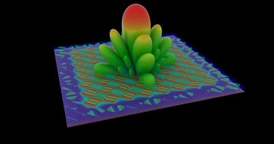
La radiazione di un'antenna ad array a fasi deriva dal movimento di correnti elettriche e magnetiche sulle antenne che lo compongono in un ritardo di fase/tempo prescritto. I colori delle antenne sul piano dell'antenna in questo modello di simulazione del software HFSS indicano il movimento relativo delle correnti di superficie sulle antenne, mentre la rappresentazione 3D della superficie mostra la radiazione dell'antenna rispetto alla direzione di puntamento.
La simulazione può aiutare a:
- Verificare il progetto dell'antenna rispetto alla tecnologia di processo prevista.
- Verificare i potenziali errori di produzione.
- Analizzare le prestazioni delle antenne in scenari reali, inclusi ambienti estremi (come la Death Valley o lo spazio) e scenari applicativi (ad esempio, il montaggio dell'antenna su un aeroplano militare per monitorarne le prestazioni o in una città per verificare la copertura delle reti wireless in luoghi diversi).
- Verificare la fisica e le proprietà dei materiali fondamentali in diverse condizioni.
- Verificare il sistema dell'antenna per controllare la perdita delle prestazioni in caso di guasto di un singolo canale. In questo modo è possibile programmare e pianificare strategicamente le riparazioni per ridurre al minimo l'impatto sui sistemi operativi.
È possibile utilizzare una serie di strumenti Ansys per rispondere a queste domande:
- Software di simulazione elettromagnetica ad alta frequenza Ansys HFSS: Utilizzato per progettare tecnologie ad alta frequenza a livello di dispositivo e integrazione, e array a fasi in cui vengono calcolati tutti i pesi richiesti per concentrare un fascio in una particolare direzione.
- Software di simulazione del raffreddamento di elettronica Ansys Icepak: Progettato per misurare il calore connettivo attorno ai sistemi di antenne e sviluppare sistemi di raffreddamento per l'applicazione.
- Software di simulazione dei fluidi Ansys Fluent: Utilizzato per modellare sistemi raffreddati tramite fluido, aria e acqua al fine di consentire un funzionamento ottimale ed evitare il surriscaldamento di transistor e chip.
- Software di modellazione dei canali wireless ad alta fedeltà Ansys RF Channel Modeler: Progettato per combinare i gemelli digitali dei sistema di antenne con i gemelli digitali di un ambiente su larga scala per osservare il funzionamento degli array RF in scenari reali.
Il futuro del beamforming
Sebbene la tecnologia beamforming permetta oggi a molti sistemi di antenne di raggiungere prestazioni molto più elevate, i progressi nel beamforming digitale stanno trasformando la tecnologia di comunicazione di nuova generazione.
Questo perché il segnale viene inviato a un formato digitale il più rapidamente possibile e, in seguito, i processori digitali ad alta velocità creano più fasci per cercare la direzione desiderata. Con un'elaborazione in banda base sufficiente, fase e ampiezza possono essere applicate a tutti gli utenti, in modo che ciascuno disponga del proprio fascio.
Mentre il 5G sta già traendo vantaggi dal beamforming, il beamforming digitale permetterà di introdurre tecnologia 6G, sistemi radar più avanzati, beamforming MU-MIMO (multiple-user multiple-input multiple-output) e beamforming olografico.
Se desideri scoprire come puoi progettare array di antenne e sistemi di comunicazione più avanzati utilizzando diversi approcci di beamforming, contatta il nostro team tecnico oggi stesso.
Risorse correlate
Cominciamo
Se devi affrontare sfide di progettazione, il nostro team è a tua disposizione per assisterti. Con una vasta esperienza e un impegno per l'innovazione, ti invitiamo a contattarci. Collaboriamo per trasformare i tuoi ostacoli ingegneristici in opportunità di crescita e successo. Contattaci oggi stesso per iniziare la conversazione.