-
-
Software gratuito per studenti
Ansys potenzia la nuova generazione di ingegneri
Gli studenti hanno accesso gratuito a software di simulazione di livello mondiale.
-
Connettiti subito con Ansys!
Progetta il tuo futuro
Connettiti a Ansys per scoprire come la simulazione può potenziare la tua prossima innovazione.
Paesi e regioni
Customer Center
Supporto
Partner Community
Contatta l'ufficio vendite
Per Stati Uniti e Canada
Accedi
Prove Gratuite
Prodotti & Servizi
Scopri
Chi Siamo
Back
Prodotti & Servizi
Back
Scopri
Ansys potenzia la nuova generazione di ingegneri
Gli studenti hanno accesso gratuito a software di simulazione di livello mondiale.
Back
Chi Siamo
Progetta il tuo futuro
Connettiti a Ansys per scoprire come la simulazione può potenziare la tua prossima innovazione.
Customer Center
Supporto
Partner Community
Contatta l'ufficio vendite
Per Stati Uniti e Canada
Accedi
Prove Gratuite
ANSYS BLOG
March 16, 2023
From Concept to CubeSat Part 2: Using Ansys Zemax OpticsBuilder to Generate CubeSat Opto-Mechanics
In the aerospace industry, CubeSats are a low-cost, easily manufacturable solution for space-based optical systems. This blog series explains how Ansys Zemax software can be used to take a CubeSat from its initial optical design to an opto-mechanical package ready for structural-thermal-optical-performance (STOP) analysis.
After designing an optical system, the payload’s opto-mechanics can be modeled. With Ansys Zemax OpticsBuilder in Creo Parametric, exporting an optical model to a computer-aided design (CAD) environment is streamlined and intuitive. OpticsBuilder brings an optical model into Creo by generating native geometry for each optical component. With OpticsBuilder, optical simulations can also be run directly within Creo, limiting the need to transfer an optical system between optical design and CAD software. This allows for increased engineering efficiency.
Exporting Optical Designs into OpticsBuilder
In part one, the initial optical design was modeled for a CubeSat. With the optical design completed, opto-mechanics need to be designed to retain the optics to suitable tolerances. To easily build opto-mechanics into our system, the optical design can be exported from Ansys OpticStudio to a CAD environment via OpticsBuilder.
To export the optical design, use the Prepare for OpticsBuilder tool in OpticStudio. When exported, OpticStudio packages all relevant information into a .ZBD file and automates a few tasks for you. To learn more about the Prepare for OpticsBuilder tool, read the corresponding knowledgebase article on the Ansys Zemax website.
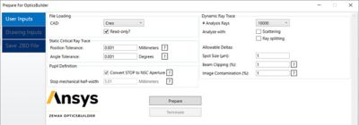
Figure 1. The Prepare for OpticsBuilder tool
This tool confirms that all surfaces and objects in the optical design are compatible with Creo before running a ray trace to analyze system performance. The results of this ray trace are used as a point of comparison once the .ZBD file is imported into OpticsBuilder. When the file is imported into OpticsBuilder within Creo, a second simulation is performed by dynamically running a new ray trace. This ray trace verifies that the system performance of the imported optical system has not changed.
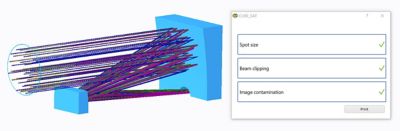
Figure 2. Ray trace simulation after importing into OpticsBuilder
Opto-Mechanical Considerations for a CubeSat Design
Next, the external CubeSat frame and opto-mechanics need to be designed. There are several considerations to be made during this section of the design process, including:
- Payload size constraints
- In-orbit operational temperature and pressure conditions
- Vibration loads experienced by the payload during launch into orbit
- Thermal expansion/contraction resulting from material selection
- Baffling design for combating stray light
- Ensuring the opto-mechanical design does not interfere with the beam path
OpticsBuilder’s simulation tool set and capacity for importing optics into CAD as native geometry allows for a streamlined opto-mechanical design workflow. Eliminating the need to continuously transfer a design between optical design software and CAD for specific tasks allows for tackling these design challenges with increased efficiency.
Design of CubeSat Opto-Mechanics
For this CubeSat workflow example, the opto-mechanics were designed to a standard CubeSat form factor of 3 Units (U). 1 U of space is equivalent to 10 by 10 by 10 centimeters. The CubeSat standard was created by Stanford University’s Space Systems Development Lab and California Polytechnic State University, San Luis Obispo. More information on the developed standard can be found here.
First, the external frame of the 3-U CubeSat was sketched in Creo Parametric. The following picture displays the external frame without any optics present.
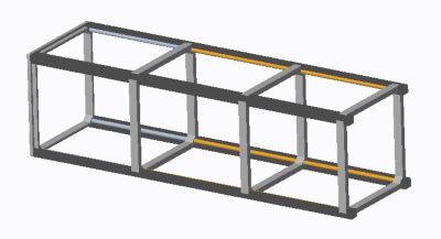
Figure 3. External frame for a 3-U CubeSat
With the external frame developed, the optical design was housed within the structure. Opto-mechanics were then built to retain the optics and mate them to the external frame.
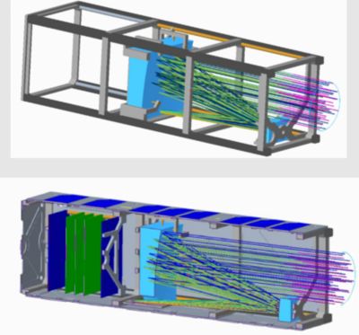
Figure 4. Completed opto-mechanical design for a 3-U CubeSat
With the opto-mechanical design finalized, the impact of these components on optical performance can be simulated within Creo Parametric with the Simulation tool. For the final simulation, the full opto-mechanical model was encased with solar panel shielding.
The ray trace simulation verified that the opto-mechanics did not have a significant impact on optical performance. The fully built system can now be exported to finite element analysis (FEA) software to begin STOP analysis.
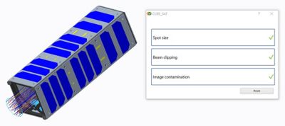
Figure 5. Ray trace simulation of final opto-mechanical design.
With OpticsBuilder, the gap has been bridged between optical engineering and mechanical engineering. With a streamlined and intuitive workflow, engineering teams can be more efficient in tackling the challenges of opto-mechanical design.
For a more in-depth look at this portion of the CubeSat design workflow, read the corresponding knowledgebase article on the Zemax website.