Synopsys and Ansys power the future of innovation—connecting silicon to systems.
-
-
Software gratuito per studenti
Ansys potenzia la nuova generazione di ingegneri
Gli studenti hanno accesso gratuito a software di simulazione di livello mondiale.
-
Connettiti subito con Ansys!
Progetta il tuo futuro
Connettiti a Ansys per scoprire come la simulazione può potenziare la tua prossima innovazione.
Customer Center
Supporto
Partner Community
Contatta l'ufficio vendite
Per Stati Uniti e Canada
Accedi
Prove Gratuite
Prodotti & Servizi
Scopri
Chi Siamo
Back
Prodotti & Servizi
Back
Scopri
Ansys potenzia la nuova generazione di ingegneri
Gli studenti hanno accesso gratuito a software di simulazione di livello mondiale.
Back
Chi Siamo
Progetta il tuo futuro
Connettiti a Ansys per scoprire come la simulazione può potenziare la tua prossima innovazione.
Customer Center
Supporto
Partner Community
Contatta l'ufficio vendite
Per Stati Uniti e Canada
Accedi
Prove Gratuite
ANSYS BLOG
August 25, 2020
Top 3 New HFSS Features for 5G Antenna Design
5G networking, with its higher data rates, greater capacity, broader bandwidth, increased security and lower latency, will bring new and unprecedented wireless experiences, products and entire industries to the world.
5G enabling technologies will also bring about new challenges for designers of both networking infrastructure and 5G client devices. A core feature of these challenges undoubtedly will be the antenna systems and their integration into the client product or networking platform. To achieve greater data rates and bandwidths, 5G will use higher frequency bands in the millimeter wave (mmWave) spectrum. These higher frequencies, along with technologies required for beamforming, beam steering and multiple beams (MIMO) will pose significant challenges to antenna designers and system integrators.
For decades Ansys HFSS has been at the forefront, enabling engineers to address their most difficult antenna design challenges. The recent Ansys 2020 R2 release brings new and significant improvements to HFSS, specifically addressing antenna design challenges for 5G.
Solve for Arrays with Multiple Antenna Elements
In the mmWave space, 5G antennas will be implemented as an arrangement of multiple antenna elements called an "array antenna" to increase the antenna’s effective aperture and gain. Array antennas can also steer energy or information to client devices to provide a very secure high-throughput link. Embedded electronics also have the ability to scan dynamically and track the user physically moving through the network.
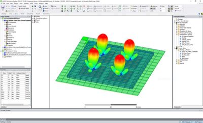
3D Comp Array solutions use the repetitive nature of a design to further simplify the meshing and solving effort without any loss in fidelity or solution accuracy.
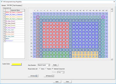
With Ansys HFSS 3D Comp Array technology you can set up 5G mmWave array antennas and efficiently solve them using a sophisticated solver technology called the domain decomposition method (DDM). In addition, 3D Comp Array solutions use the repetitive nature of the design to further simplify the meshing and solving effort without any loss in solution accuracy. More recently, the 3D Comp Array technology has been enhanced with an intuitive interface for quickly setting up these designs using multiple unique unit-cells in the array definition.
Finally, in the Ansys 2020 R2 release, the 3D Comp Array technology is enhanced to solve these complex array antenna system matrices with the direct matrix solver of HFSS. This provides the lowest possible solution noise floor with faster solution times, especially when the number of excitations or elements grow large.
3D Comp Array solutions use the repetitive nature of a design to further simplify the meshing and solving effort without any loss in fidelity or solution accuracy.
Save Time with Concurrent Meshing
Another interesting new feature that was applied in 2020 R2 is the ability to mesh all the different components assembled in a 3D Comp array in a parallel, or concurrent, fashion. Concurrent Assembly Meshing leverages both shared and distributed HPC resources and saves time by enabling faster simulation.
In addition, you can define a specific meshing technology to parts of the design. The HFSS phi mesher, which is optimized for layered structures such as printed circuit boards (PCBs) and integrated circuit (IC) packages, can be distinctly applied to those parts of a design. Similarly, the Tau mesher, better suited for “true” 3D parts, such as a connector or a housing, can be applied specifically to those parts.
Automate 5G Post-Processing
5G poses several challenges for post-processing simulation data and analyzing device performance. The cumulative distribution function (CDF) for antenna arrays is an analysis that determines your 5G array antenna’s coverage performance, whether it is a part of a client device or the networking system. Using CDF, you can quickly understand the expected overall performance of an antenna array from the design based on a set of pre-determined scan angles.
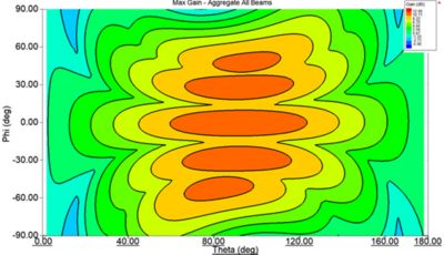
Combined 3D radiation pattern plot showing effective gain coverage over set of specified scan angles
Finally, automated extraction of power density (PD) will be very important if you are designing client devices that require specific absorption rate (SAR) certification. In developing any 5G client device, like a smartphone or a headset, the amount of energy the device might radiate into the user is quantified as the electromagnetic PD at a specified distance from the client device. This automation analyzes the PD quickly and efficiently, and gives you a good idea if you're going to pass a certification test. It indicates when you might have to set power levels back or redesign the device completely to pass certification. This technology for certifying client devices for 5G standards has already been leveraged in the electronics industry.
To learn more about 5G antenna design solutions and workflows, check out the "How to Design User Equipment Antenna Systems” and “How to Design Base Station Antenna Arrays” white papers.