-
-
Software gratuito per studenti
Ansys potenzia la nuova generazione di ingegneri
Gli studenti hanno accesso gratuito a software di simulazione di livello mondiale.
-
Connettiti subito con Ansys!
Progetta il tuo futuro
Connettiti a Ansys per scoprire come la simulazione può potenziare la tua prossima innovazione.
Customer Center
Supporto
Partner Community
Contatta l'ufficio vendite
Per Stati Uniti e Canada
Accedi
Prove Gratuite
Prodotti & Servizi
Scopri
Chi Siamo
Back
Prodotti & Servizi
Back
Scopri
Ansys potenzia la nuova generazione di ingegneri
Gli studenti hanno accesso gratuito a software di simulazione di livello mondiale.
Back
Chi Siamo
Progetta il tuo futuro
Connettiti a Ansys per scoprire come la simulazione può potenziare la tua prossima innovazione.
Customer Center
Supporto
Partner Community
Contatta l'ufficio vendite
Per Stati Uniti e Canada
Accedi
Prove Gratuite
ANSYS BLOG
September 22, 2022
Ansys Rocky’s 200-Million Particle Simulation on Oracle Cloud Pushes DEM Analysis to a New Height
Oracle Cloud Infrastructure (OCI) and NVIDIA have elevated discrete element modeling (DEM) technology via the first-of-its-kind simulation of a 200-million particle analysis using Ansys Rocky DEM software on OCI’s bare-metal graphical processing unit (GPU) shape.
The latest NVIDIA data center solution, the NVIDIA A100 Tensor Core GPU, was one of the key components in this simulation. It allowed GPU-accelerated software codes such as Rocky DEM to use its full capacity, handling tens of millions of particles deployed in a DEM simulation model. Enabled by Rocky’s multi-GPU parallel processing capabilities and the power of OCI’s bare-metal GPU systems, we can dramatically expand the range of applications and apply DEM simulations to analyze problems that include hundreds of millions of particles. In addition, in the most recent release of Rocky, a powerful parallel load balancing algorithm enables more efficient GPU resource utilization than previous versions.
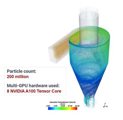
Recently, OCI and Ansys designed a study for a gas cyclone separator, a device commonly used to separate and remove particles from an airflow stream. Such a device can be found in our home vacuum cleaners and has many industrial uses, including separating abrasives, pollutants, dust particles, and various production plant exhausts.
In this study, particle-laden air was injected into a centimeter-sized cyclone. While the air swirled inside the cyclone, dust particles of different diameters bumped into each other, bouncing off the interior walls of the cyclone. The rapid swirling motion allowed the heavier particles to move toward the cyclone walls and make their way out through the bottom outlet while some finer particles and a cleaner air stream were released from the top outlet.
Looking Under the Hood
Solving a problem as big as a 200-million particle simulation demands a powerful set of computing hardware, which OCI provides in the form of a tailored cloud computing infrastructure, as illustrated in Figure 1. The muscle of this solution is the bare-metal BM.GPU4.8 server, loaded with eight NVIDIA A100 GPUs with 40 GB of GPU memory in each for a total of 320 GB in GPU memory. The Rocky solver was installed on top of Oracle Linux, an Oracle-optimized general-purpose Linux distribution that carries all required dependencies to enable the NVIDIA GPUs and Rocky DEM software.
Post-processing a large model is a compute-intensive task. For that purpose, hardware-accelerated rendering with GUI-enabled instances is a must-have, and we selected the virtual machine VM.GPU3.1, which was configured with an NVIDIA V100 Tensor Core GPU.
With the computing hardware taken care of, there was still one concern: storage of the results. Huge simulation cases tend to generate a large amount of data, which uses a lot of disk space. To avoid moving such a large amount of data between the processing server BM.GPU4.8 and the post-processing server VM.GPU3.1, a more efficient storage solution was developed. A third virtual machine was launched to serve as a network file system (NFS) server with terabyte-level block storage mounted to it. This storage solution made intermediate output data available for post-processing on the fly. It also allowed the bare-metal BM.GPU4.8 server to be deleted when the simulation work was finished, creating a more cost-effective solution. Similarly, the post-processing virtual machine could be deleted while waiting for new intermediate output data.
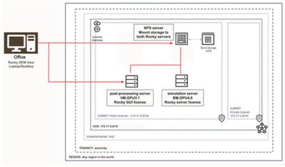
Figure 1. OCI cloud computing architecture deployed for this study.
Getting Results
The solution was obtained using a computational fluid dynamics (CFD)-DEM coupling approach. The CFD part, meaning the airflow field solution, was obtained from Ansys Fluent and used in Rocky through its one-way coupling approach. On the other end, Rocky handled the entire DEM part, as well as particle-fluid interaction computations.
The geometry of the cyclone and CFD mesh are shown in Figure 2. The cyclone was 0.3 m in height and 0.15 m in diameter, air was injected at 30 m/second, and the simulation was computed for 0.12 seconds. Particles started leaving the domain at 0.025 seconds, meaning the flow was solved for approximately five flow-through times. The dust particles carried by the airflow, sized 5-50 μm (10-6 m), were injected into the cyclone at around two billion particles/second, bringing the cyclone mass load to around 50%.
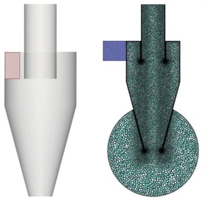
Figure 2. Cyclone geometry and computational fluid dynamics (CFD) mesh.
Simulation numbers are summarized in Table 1 below.
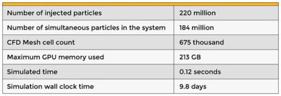
Table 1. Statistics of the gas cyclone separator simulation.
The output of the simulation can be seen below. The particle count grew quickly from zero to tens of millions, creating the expected spiral airflow pattern. The injection rate was achieved, and at the end of the simulation, a total of 184 million particles were simultaneously swirling in the cyclone. At this point, approximately 200 GB of GPU memory was used, leaving more than a third of total GPU memory unused. This is the headroom for future Rocky computation models to expand its size on OCI’s bare-metal machines.
Learn how to expand DEM-CFD coupling capabilities using Ansys Rocky and Fluent in this webinar: Multiphysics Simulation with CFD-DEM