-
-
Accédez au logiciel étudiant gratuit
Ansys donne les moyens à la prochaine génération d'ingénieurs
Les étudiants ont accès gratuitement à un logiciel de simulation de classe mondiale.
-
Connectez-vous avec Ansys maintenant !
Concevez votre avenir
Connectez-vous à Ansys pour découvrir comment la simulation peut alimenter votre prochaine percée.
Pays et régions
Espace client
Support
Communautés partenaires
Contacter le service commercial
Pour les États-Unis et le Canada
S'inscrire
Essais gratuits
Produits & Services
Apprendre
À propos d'Ansys
Back
Produits & Services
Back
Apprendre
Ansys donne les moyens à la prochaine génération d'ingénieurs
Les étudiants ont accès gratuitement à un logiciel de simulation de classe mondiale.
Back
À propos d'Ansys
Concevez votre avenir
Connectez-vous à Ansys pour découvrir comment la simulation peut alimenter votre prochaine percée.
Espace client
Support
Communautés partenaires
Contacter le service commercial
Pour les États-Unis et le Canada
S'inscrire
Essais gratuits
INFORMATIONS SUR LE SUJET
Qu'est-ce que l'analyse nodale ?
L'analyse nodale est une méthode de calcul de la tension au niveau des connexions, appelées nœuds, entre les composants d'un circuit électrique. C'est un élément essentiel de l'analyse des circuits, qu'il s'agisse d'un circuit câblé simple reliant des composants discrets ou de circuits intégrés (CI) en semi-conducteurs complexes.
Dans une analyse nodale simple, chaque connexion entre les composants, les tracés ou les fils est appelée nœud. Les lois de Kirchhoff et d'Ohm sont utilisées pour écrire des équations reliant la résistance, le courant et la tension de chaque chemin conducteur menant à chaque nœud. Le système d'équations est ensuite résolu à la main ou en utilisant l'algèbre linéaire pour la chute de tension à chaque nœud. Pour les problèmes plus importants, un logiciel, généralement sous la forme d'un simulateur de circuit SPICE, est utilisé pour effectuer l'analyse nodale.
Les lois fondamentales de l'analyse nodale
La méthode d'analyse nodale est basée sur l'utilisation de trois lois fondamentales :
1. Loi des noeuds de Kirchhoff (KCL)
La somme algébrique de tous les courants entrant et sortant d'un nœud doit être égale à zéro.
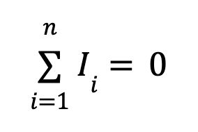
Où I est le courant et n est le nombre de branches alimentant le nœud.
2. Loi des mailles de Kirchhoff (KVL)
La somme algébrique de toutes les différences de potentiel (tensions) dans une boucle doit être égale à zéro.
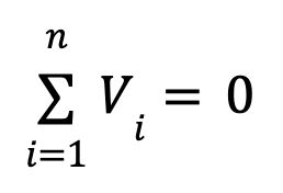
Où V est la tension et n est le nombre d'endroits où la tension est mesurée autour de la boucle.
3. Loi d'Ohm
Le courant électrique (I) traversant un conducteur est égal à la tension (V) aux bornes du conducteur divisée par la résistance (R) du conducteur.
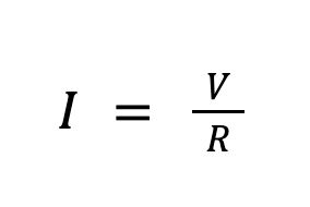
Terminologie de l'analyse nodale
Pour une analyse nodale, un schéma de circuit est utilisé pour représenter un réseau des éléments suivants :
Nœud de référence : Nœud du circuit dans lequel la tension est connue. Il s'agit généralement d'un nœud de masse et la tension est définie sur 0.
Nœud sans référence : tout nœud dans lequel la tension est inconnue
Source de tension : composant du circuit dans lequel le potentiel est modifié par une tension connue
Source de courant : composant avec un courant connu
Supernœud : Lorsqu'une source de tension a deux tensions inconnues de part et d'autre, elle peut être transformée en supernœud, dans lequel les courants des deux nœuds sont combinés en une seule équation. Une nouvelle équation pour la relation tension-courant du supernœud peut alors être écrite.
Composant : Dispositif électronique avec une relation connue entre la tension et le courant. Pour une résistance, cette relation est basée sur la résistance. Elle est souvent exprimée comme admittance, ou l'inverse de la résistance. Pour un condensateur, la relation dépend de la relation entre la capacité et le changement de tension dans le temps.
Analyse nodale modifiée : Pour les circuits plus complexes, une simple analyse nodale peut ne pas suffire à trouver toutes les tensions inconnues. Dans les cas où la relation courant-tension d'un composant est plus compliquée que la loi d'Ohm, une analyse nodale modifiée est effectuée.
Analyse de maillage : Si les courants ne sont pas connus, la loi de tension de Kirchhoff est utilisée dans ce qu'on appelle une analyse de maillage pour trouver les courants de branche inconnus.
Pourquoi l'analyse nodale est-elle importante ?
Les circuits électroniques sont conçus pour transférer le courant électrique afin de fournir la puissance et un signal. Les ingénieurs qui conçoivent des circuits doivent savoir que l'électronique qu'ils définissent fonctionne comme prévu. Une analyse nodale est effectuée pour calculer les tensions de nœud et les flux de courant pour chaque partie du circuit. Une fois ces valeurs fondamentales connues, une analyse plus complexe peut être effectuée pour comprendre l'intégrité du signal, l'échauffement et la performance énergétique globale.
Pour les conceptions au niveau des circuits imprimés, l'analyse nodale peut être utilisée pour comprendre l'impact de la topologie du circuit, l'effet des différents composants et la distribution globale de la puissance sur les chemins de conductance tels que les plans de masse, les tracés et les vias.
Pour les micropuces de tout type, la compréhension des pertes de puissance devient encore plus importante. Le nombre d'équations nodales peut devenir significatif en raison du nombre de nœuds. La compréhension et la vérification de la distribution du courant, de la tension et de la puissance ne peuvent être accomplies que par l'analyse du circuit.
Le calcul des chutes de tension est une autre application fréquente de l'analyse nodale, en particulier dans les produits semi-conducteurs complexes d'aujourd'hui. Chaque fois qu'une baisse de potentiel se produit entre les nœuds, de la chaleur est produite et l'énergie qui pourrait être utile ailleurs est dissipée. Les outils d'analyse nodale sont utilisés même sur les semi-conducteurs les plus complexes pour identifier les faiblesses du circuit causées par des chutes de tension indésirables ou concentrées.
Les concepteurs de puces peuvent utiliser ces outils non seulement pour détecter les problèmes, mais aussi pour réaliser des études de scénarios hypothétiques afin d'optimiser la puissance et les performances. Des outils comme la plateforme de validation de l'intégrité énergétique Ansys RedHawk-SC™ pour les circuits intégrés numériques et 3D fonctionnent sur de grandes plateformes Cloud HPC pour prendre en charge de grands circuits avec des millions de composants dans la toute dernière architecture de semi-conducteurs. Parce qu'il s'agit d'une méthode fiable, de nombreuses fonderies majeures certifient les logiciels RedHawk-SC pour la validation.
Étapes utilisées pour effectuer une analyse nodale
Qu'elle soit effectuée manuellement ou automatisée dans un logiciel, une analyse nodale suit la procédure suivante :
1. Définir les nœuds
Capturer tous les segments conducteurs connectés dans les circuits (les nœuds). En cas de résolution manuelle, dessiner le circuit et numéroter les nœuds. En cas d'utilisation d'un logiciel, une liste de tous les nœuds et de leur connectivité aux composants est créée par programmation à partir d'un schéma.
2. Choisir un nœud de terre
Sélectionner un nœud comme nœud de référence et définir sa tension comme tension de terre. Cela réduit d'une unité le nombre d'inconnues dans le système. Si vous avez n nœuds, vous devez alors résoudre n-1 équations.
3. Créer des variables
Pour chaque nœud sans référence avec une tension inconnue, attribuer une variable pour indiquer la tension de ce nœud. Les nœuds avec une tension connue n'ont pas besoin d'une variable.
4. Construire des équations de nœud
Parcourir chaque nœud avec une tension inconnue et écrire l'équation KCL pour ce nœud. Cela consiste à additionner les courants de branche calculés pour chaque branche du nœud et à mettre cette somme à zéro. Le courant entre deux nœuds peut être une valeur connue si une source de courant se trouve entre les nœuds. Il s'agit de la différence de tension entre les nœuds divisée par la résistance entre les nœuds, ou il peut s'agir d'une relation entre la variation de tension et la capacité pour un condensateur. D'autres composants peuvent avoir des équations plus complexes.
5. Joindre des nœuds en tant que supernœuds
Combiner toutes les sources de tension connectant deux tensions inconnues dans des supernœuds avec une seule équation.
6. Assembler et résoudre
À moins que le circuit ne soit assez petit pour être résolu manuellement, le système d'équations simultanées peut être réarrangé en une matrice carrée composée de n-1 colonnes et lignes. Les méthodes numériques d'algèbre linéaire peuvent ensuite être utilisées pour résoudre les tensions inconnues.
Quelques exemples simples d'analyse nodale
Voici un exemple simple pour mieux illustrer ce processus. L'illustration ci-dessous montre un circuit avec une source de courant, une source de tension de 10 volts et deux résistances. La tension V1 n'est pas connue.
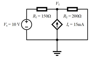
- V1 est la seule tension inconnue. L'autre nœud est connecté à la terre et sera notre point de référence.
- Le nœud V1 comprend trois courants de branche :
- Le courant passant par la résistance R1 : (V1 - Vs)/R1
- Le courant passant par la résistance R2 : (V1 - 0)/R2
- Le courant passant par la source de courant ls : - Is
- En appliquant la loi des courants de Kirchhoff, nous les additionnons et les définissons à 0 :

4. Réécrire par rapport à V1 :

Utilisons maintenant la méthode d'analyse nodale pour examiner un circuit avec une source de tension connectée à deux tensions inconnues.
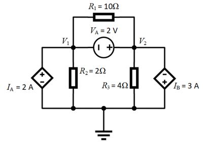
- V1 et V2 ont une tension nodale inconnue. L'autre nœud est relié à la terre et sera notre nœud de référence à 0 volt. De plus, VA est compris entre V1 et V2, il s'agit donc d'un supernœud.
- Le nœud V1 comprend trois courants de branche :
- Le courant passant par la résistance R1 : (V1 - V2)/R1
- Le courant passant par la résistance R2 : (V1 - 0)/R2
- Le courant passant par la source de courant IA : - IA ou 2 ampères
- Le nœud V2 comprend quatre courants de branche :
- Le courant passant par la résistance R1 : (V2 - V1)/R1
- Le courant passant par la résistance R2 : (V2 - 0)/R3
- Le courant passant par la source de courant Ib : Ib ou 2 ampères
- L'équation du supernœud pour VA : V2 = V1 + VA
- En appliquant la loi des courants de Kirchhoff, nous additionnons les flux de courant pour le nœud 1 et les définissons à 0 :

5. Réécrire par rapport à V1 :
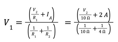
6. En appliquant la loi des courants de Kirchhoff, nous additionnons les flux de courant pour le nœud 2 et les définissons à 0 :

7. Réécriture par rapport à V2.
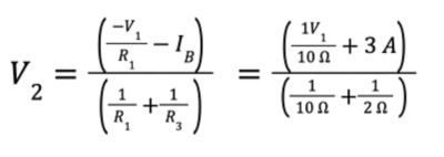
8. En utilisant l'équation du supernœud pour V2 et en résolvant les deux autres équations, nous obtenons V1 = -7,33 V et V2 = -5,33 V
Initiation à l'analyse nodale des systèmes électriques complexes
L'analyse nodale, généralement sous la forme d'un solveur SPICE, est une étape fondamentale dans la caractérisation du comportement de tout circuit électrique. Des circuits simples sur une carte d'expérimentation aux derniers semi-conducteurs de l'industrie avec des millions de transistors, les ingénieurs doivent utiliser des outils tels que la plateforme de validation d'intégrité énergétique Ansys Totem™ pour non seulement calculer les tensions, mais également utiliser ces informations pour comprendre le bruit de puissance et obtenir une validation de fiabilité pour les conceptions analogiques à signaux mixtes.
Le logiciel Ansys Twin Builder® offre un solveur d'analyse nodale complet qui peut être combiné avec d'autres outils d'ordre réduit. Grâce à lui, il est possible d'analyser votre circuit et ce à quoi il est attaché dans votre produit, le tout dans une seule interface.
Voici quelques suggestions pour rendre l'application de l'analyse nodale aux systèmes électriques complexes efficace et réussie :
- Prenez connaissance de tous les éléments du circuit dans votre conception avant de créer votre modèle d'analyse nodale, y compris leurs caractéristiques électriques.
- Assurez-vous que vos hypothèses sur les nœuds de référence sont correctes, qu'ils sont vraiment mis à la terre et que la tension ne peut pas fluctuer.
- Assurez-vous d'utiliser un outil capable de lire vos données ECAD de manière transparente et ne nécessitant qu'une intervention minimale de l'utilisateur pour construire votre représentation de circuit.
- Prenez le temps de comprendre les bases de l'analyse nodale. Prenez le temps d'explorer des tutoriels traitant de l'analyse simple des circuits, en lien avec les composants que vous devez caractériser.
- Utilisez un outil logiciel capable de réaliser plus qu'une analyse nodale. Optez pour une solution qui prend l'analyse nodale d'un circuit donné comme point de départ pour des simulations ultérieures.
Ressources connexes
Commençons
Si vous êtes confronté à des défis d'ingénierie, notre équipe est là pour vous aider. Forts de notre expérience et de notre engagement en faveur de l'innovation, nous vous invitons à nous contacter. Collaborons pour transformer vos obstacles techniques en opportunités de croissance et de réussite. Contactez-nous dès aujourd'hui pour entamer la conversation.