Synopsys and Ansys power the future of innovation—connecting silicon to systems.
-
-
Accédez au logiciel étudiant gratuit
Ansys donne les moyens à la prochaine génération d'ingénieurs
Les étudiants ont accès gratuitement à un logiciel de simulation de classe mondiale.
-
Connectez-vous avec Ansys maintenant !
Concevez votre avenir
Connectez-vous à Ansys pour découvrir comment la simulation peut alimenter votre prochaine percée.
Espace client
Support
Communautés partenaires
Contacter le service commercial
Pour les États-Unis et le Canada
S'inscrire
Essais gratuits
Produits & Services
Apprendre
À propos d'Ansys
Back
Produits & Services
Back
Apprendre
Ansys donne les moyens à la prochaine génération d'ingénieurs
Les étudiants ont accès gratuitement à un logiciel de simulation de classe mondiale.
Back
À propos d'Ansys
Concevez votre avenir
Connectez-vous à Ansys pour découvrir comment la simulation peut alimenter votre prochaine percée.
Espace client
Support
Communautés partenaires
Contacter le service commercial
Pour les États-Unis et le Canada
S'inscrire
Essais gratuits
ANSYS ADVANTAGE MAGAZINE
DATE: 2020
Faster than the Wind
By Steve Collie, Aerodynamics Engineer, Emirates Team New Zealand, Auckland, New Zealand
"The integrated suite of Ansys multiphysics tools — fluids, structural and composites simulation — helps ETNZ smooth the way."
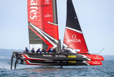
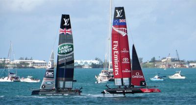
The America’s Cup, the premier event in the elite sport of yacht racing, is eagerly anticipated by fans. Held every few years since 1851, boats and sailors from around the world compete to win the highly prized trophy. The next event is slated for 2017 in Bermuda. The exciting race is a physical and mental challenge for the crew, but behind the scenes and before the race, America’s Cup boats require extensive engineering that must occur on a tight schedule. Because physical testing of all possible improvements to a vessel of this complexity is inconceivable (not to mention financially untenable), Emirates Team New Zealand (ETNZ) has turned to Ansys multiphysics engineering simulation software to develop a reliable, robust and competitive craft.
Aerospace technology — including advanced aerodynamics, lightweight materials, wind tunnel testing and advanced simulation technology — has revolutionized the sport of America’s Cup racing. Today’s cup-class yachts use a wing that is more akin to an airplane’s wing or airfoil than to a traditional sail. The wing enables the catamarans to transfer wind into forward momentum (instead of into lift, as in aircraft).
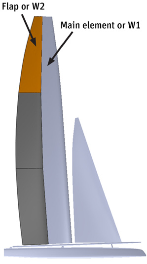
WING DESIGN
The wings are two-element airfoils comprising a main element along with a flap unit that is hinged from the back of the main element. This main element is a rigid structure that makes up the leading edge of the wing, which is the primary structural spar. The flap incorporates three segments that can be cambered to increase lift by changing the angle between the main element and the flap. Individual flap segments can be twisted to depower individual segments and change the center of aerodynamic pressure. Hydraulic actuators are used to camber and twist flap segments into the most efficient aerodynamic shape based on prevailing sailing conditions.
Simple model of single segment of flap used in stage 1 simulation
Race rules fix many aspects of the design of these yachts, such as hull shape, wing shape and deck layout. So, beyond the contribution that a skilled crew offers, the America’s Cup is largely won or lost based on the ability of the underlying systems, including the wing structure, to deliver optimal performance under a wide range of sailing conditions. Emirates Team New Zealand engineers, who bounced back from a narrow loss in the last race in 2013, were under enormous time pressure to design these systems for a new test yacht within a five-month time frame to stay on track with their schedule leading up to the 2017 competition. Using Ansys fluid–structure interaction (FSI) multiphysics and composites simulation, ETNZ is able to virtually test hundreds of variations early in the process to find the optimal design before performing any physical testing. Testing using the actual boat is time-consuming and expensive, and it would not be possible to physically test all design trade-offs without simulation.
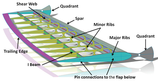
WING STRUCTURE
Both the main element and the flap are built using lightweight ribs and a spar covered with thermoplastic film. The flap element itself comprises three sections — flap 1, flap 2 and flap 3 — running from bottom to top. Hydraulic actuators that pull and ease control lines are connected to control stations at the top and bottom of each flap section.
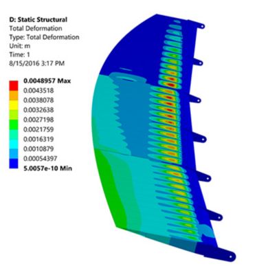
The ability to quickly and efficiently control flap twist is critical for fast, accurate, well-controlled sailing. Flap deformation must be optimized to provide the desired span-wise lift distribution while achieving weight targets. Extreme twist leads to large strains in the flaps. For example, flap 3 twists as much as 20 degrees across its length. Because of these large deformations — and a thermal boundary condition used to pre-tension the thermoplastic membranes on the surface of the wing — optimization requires nonlinear structural analysis.
"Today’s America’s Cup–class yachts use a wing that is more akin to an airplane’s wing or airfoil than to a traditional sail."
PREDICTING AERODYNAMIC PRESSURES
To determine aerodynamic pressure using Ansys CFD simulations, ETNZ engineers started with computer-aided design (CAD) models of the main element and flap. They twisted the CAD model to the full range of allowable flap shapes and created inverse-domain models for flow analysis. They simulated the performance of each shape under a wide range of wind speeds and angles, as well as boat states. The results were formulated into a matrix that was used in a performance simulator to predict boat performance based on wind conditions, trim of the wing, direction into the wind and more. Ansys DesignXplorer minimized the number of simulations required to accurately represent the parameter space. This analysis required assessing the impact of an extremely large number of variables. The open Ansys framework allowed the complete simulation process to be fully automated using in-house scripts.
CAD model of wing
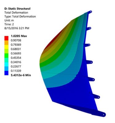
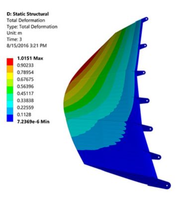
STRUCTURAL SIMULATION
The flap design process began with an initial geometry proposal defined in CAD. Using Ansys Workbench, engineers built the structural finite element model. The flaps are made of lightweight composites, so the complete layup was designed and optimized using Ansys Composite PrepPost. To set up a one-way FSI simulation, pressures from the many CFD analyses were imported and mapped onto the structure. Because CFD simulations are carried out based on the deformed wing shape, pressure data must be transformed to the undeformed wing shape, using scripts written by ETNZ engineers, so that it can be applied to the structural model. Pressures can then be mapped to the structure using Ansys Mechanical. This process and model were developed with the assistance of technical experts from Ansys and channel partner LEAP Australia, which enabled ETNZ to meet the tight deadlines.
ETNZ engineers progressively increased the complexity of their structural models. Stage 1 was a simple model of a single flap used for structural design. Stage 2 was a combined model of all three flaps that was used primarily to design the connection geometry. In stage 3, pressures determined by CFD simulations were used to load the model developed in Stage 2. This analysis determined the loads required to articulate the flaps, which were, in turn, used to design the hydraulic actuators and control system.
The team ran hundreds of iterations to optimize the geometry and laminate structure to achieve target shapes and minimize input moments under specified loading conditions. At the same time, effort was made to minimize the weight of the structure while ensuring that it could withstand the loads expected during a race.
THE BOAT LAUNCHES AND DESIGN CONTINUES
The designs described were used on a 45-foot test boat launched in summer 2016. Meanwhile, ETNZ engineers are in the process of creating a more comprehensive model that includes the main element and its connection to the yacht; it will later be expanded to the yacht structure itself. Engineers will use this model for detailed design of the main element along with bidirectional FSI to analyze the effects of the structure on the aerodynamics of the wing. Bidirectional FSI analysis will make it possible, for the first time, to investigate the wing’s dynamic response, when it is struck by a gust of wind, when the sail is being trimmed, or when the boat undergoes maneuvers like gybes and tacks.
The current design will achieve speeds approximately four times faster than boats racing in the America’s Cup 10 years ago. The main reason for this increase is that Cup teams now race catamarans, rather than the monohulls used in the past. Flying the boat on its foils (foiling) also has increased top speeds dramatically. Moving from sails to wings provides a further substantial speed improvement.
Converting wind to speed while wasting as little energy as possible is no easy task. ETNZ uses a 100-percent simulation-driven development process to test thousands of alternatives to meet its design goals for the wing, including accurate and fast control while keeping within weight targets. The integrated suite of Ansys multiphysics tools that includes fluids, structural and composites simulation helps ETNZ smooth the way. The end goal is to repeat its successes of 1995 and 2000 and bring the cup back home to New Zealand.
Emirates Team New Zealand is supported by Ansys channel partner LEAP Australia and composites design specialists from Ansys.
POWERING ENGINEERING
Teams in elite sports like Formula One racing and yachting must push their equipment to the highest level of performance to remain competitive. They adopt the best technology from every realm and push the envelope to gain an edge. Engineering simulation has been embraced in these sports because it allows team engineers to virtually test multiple design variations to gain the best possible results long before the equipment is built.
In the case of an Americas Cup yacht, converting wind to forward momentum while wasting as little energy as possible is not much different from driving a wind turbine to generate power. They both require capturing the wind to create energy; if more is captured (and controlled), a better result is achieved. The same is true of any turbine (whether driven by gas, wind, steam or water) to generate electricity or to propel an aircraft. And, just like a yacht, an F1 car or an aircraft, aerodynamics and weight contribute to how much energy is consumed.
Engineering simulation is critical to any engineer designing on the leading edge of breakthrough energy innovation — whether in industry, sport or academic research.