-
-
Accédez au logiciel étudiant gratuit
Ansys donne les moyens à la prochaine génération d'ingénieurs
Les étudiants ont accès gratuitement à un logiciel de simulation de classe mondiale.
-
Connectez-vous avec Ansys maintenant !
Concevez votre avenir
Connectez-vous à Ansys pour découvrir comment la simulation peut alimenter votre prochaine percée.
Pays et régions
Espace client
Support
Communautés partenaires
Contacter le service commercial
Pour les États-Unis et le Canada
S'inscrire
Essais gratuits
Produits & Services
Apprendre
À propos d'Ansys
Back
Produits & Services
Back
Apprendre
Ansys donne les moyens à la prochaine génération d'ingénieurs
Les étudiants ont accès gratuitement à un logiciel de simulation de classe mondiale.
Back
À propos d'Ansys
Concevez votre avenir
Connectez-vous à Ansys pour découvrir comment la simulation peut alimenter votre prochaine percée.
Espace client
Support
Communautés partenaires
Contacter le service commercial
Pour les États-Unis et le Canada
S'inscrire
Essais gratuits
Ansys Blog
March 12, 2019
Why Switching to Composite Materials Requires a New Product Design
When engineers are tasked to turn a metal part into one made from composite materials, it’s tempting to use the same geometry with a lay-up that has carbon fibers evenly distributed in all directions (aka quasi-isotropic) and then call it a day.
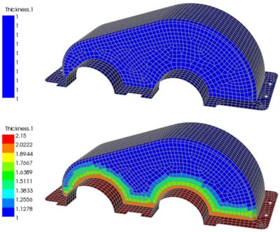
Engineers designing composite parts need to put stiffness where it is
needed. A uniform thickness, “black metal” part (top) versus a locally
reinforced part (bottom)
When engineers replace aluminum with quasi-isotropic laminates of carbon fiber reinforced plastic, the design methodology is dubbed “black metal design” for the dark color of the composite material. This design strategy will not yield a part with optimal characteristics.
While black metal substitution is common, engineers are not fully harnessing the benefits of composite materials — one being that they are strong along the fiber direction.
However, with the use of a few simulation techniques, engineers can design a high-performance composite structure that replaces the original product design.
Limitations of Black Metal Product Design
There are numerous reasons why engineers pursue the black metal design approach. For one, the established guidelines make the design process straightforward.
The challenge is that assessing the strength of a composite structure is more complex than assessing the strength of a metal structure. This is because the layered composites are made out of multiple plies, each with different spatial extents and angles. Dedicated composite simulation tools will help overcome this challenge.
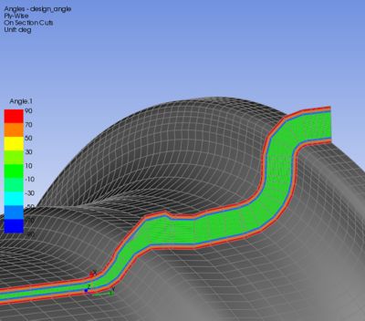
Ply-based modeling allows
engineers to simulate as-built,
real-world products
Additionally, simulations are not restricted to the realm of structural performance. They can also assess the feasibility of manufacturing a composite part. For example, simulations can model draping effects and curing processes.
There are two modeling approaches used to simulate composites: zone-based and ply-based modeling. The former can be restrictive while the latter appears to have a lot of overhead. In reality, ply-based modeling protects the design from over-simplifications. It also allows engineers to set up models that represent the as-built, real-world product. As the design evolves, ply-by-ply modeling provides more flexibility.
Therefore, ply-based modeling can help engineers devise a new optimal lay-up design for the composite part.
Challenges with Ply-Based Modeling of Composite Material Parts
A complex lay-up can make it challenging to determine the strength of a composite material part.
For a quasi-isotropic, black-metal lay-up, it is common to assess the principal strains on the outer surface of the part. However, to fully harness the capabilities of a composite design, the structural response on a ply-by-ply level is necessary.
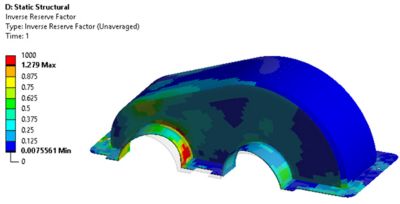
Composite failure at a glance —
the worst result through the thickness
is projected to the outside
Another challenge is that the composite’s matrix and fibers exhibit different strengths and can fail in different ways. Therefore, the failure criteria for a composite material part needs to take complex stresses and failure modes into account.
Once a comprehensive set of failure criteria are set, engineers can begin to test the composite design and push it to its performance limits. If the engineers assume that the composite material is uniform, as with a black metal, they will not be able to accurately assess the part’s performance.
How to Avoid and Overcome Distortion when Manufacturing Composites
A light, load-tailored lay-up is unlikely to be symmetric and balanced. Sometimes asymmetric lay-ups are deliberately used to control the buckling behavior when the part is in use. However, the manufacturing of these lay-ups can be challenging.
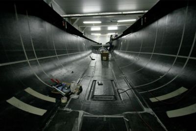
Engineers designing this composite sailing yacht need to account
for the internal stresses and distortion
The more nonuniform and the more asymmetric the lay-up is, the more prone the part is to distortion during the manufacturing process. As a thermosetting matrix surrounding the fibers cures, it undergoes phase changes. This creates internal stresses because each layer cures at a different point in time. These internal stresses can lead to the part experiencing premature failures.
Black metal, uniformly thick parts are not exempt from these risks; however, with manufacturing experience, they tend to be less pronounced and easier to correct.
For composites, engineers need to use simulation to assess how the part’s curing cycle forms internal stresses. This way, the engineer can account for the stresses during the part’s development cycle. Engineers can use this data to plan the asymmetry of each layer to limit distortions. The engineers can also invert the simulated stresses to create a manufacturing process that compensates for the distortions. In other words, simulation is key to design a composite material part so it distorts to the desired shape every time.
Load-tailored composite design and ply-by-ply modeling is undoubtedly accompanied by challenges. Ansys simulations can help overcome these challenges.
For more information, read Ansys’ solution page for Composite Materials.
To learn more about black metal, visit JEC World to speak to Ansys, Ansys GRANTA and LMAT representatives or attend the technical conference: Simulation: the end of “black metal."