Synopsys and Ansys power the future of innovation—connecting silicon to systems.
-
-
Accédez au logiciel étudiant gratuit
Ansys donne les moyens à la prochaine génération d'ingénieurs
Les étudiants ont accès gratuitement à un logiciel de simulation de classe mondiale.
-
Connectez-vous avec Ansys maintenant !
Concevez votre avenir
Connectez-vous à Ansys pour découvrir comment la simulation peut alimenter votre prochaine percée.
Espace client
Support
Communautés partenaires
Contacter le service commercial
Pour les États-Unis et le Canada
S'inscrire
Essais gratuits
Produits & Services
Apprendre
À propos d'Ansys
Back
Produits & Services
Back
Apprendre
Ansys donne les moyens à la prochaine génération d'ingénieurs
Les étudiants ont accès gratuitement à un logiciel de simulation de classe mondiale.
Back
À propos d'Ansys
Concevez votre avenir
Connectez-vous à Ansys pour découvrir comment la simulation peut alimenter votre prochaine percée.
Espace client
Support
Communautés partenaires
Contacter le service commercial
Pour les États-Unis et le Canada
S'inscrire
Essais gratuits
ANSYS BLOG
November 23, 2021
Optimize 5G Antenna Design and Solve Large Communication Challenges with Ansys HFSS
A surgeon in Boston connects with a surgeon in Bangalore to help guide him through a life-saving surgery as it is happening in real time. A self-driving vehicle suddenly brakes in anticipation of what the driver cannot see just around the next corner. These are just two of the many possibilities 5G brings into our connected lives.

The Evolution of Antenna Technology
Antenna technology has taken a giant leap from 4G to 5G to accommodate higher-frequency applications delivering greater bandwidth. In 4G, a traditional antenna receives energy from all directions and is not particularly discriminating. A lot of antennas on existing 4G handsets, for example, are omni directional. A 4G antenna operates at lower frequencies (6 GHz) that can diffract or bend around objects and be picked up very easily.
By using a beamforming method (putting two or more of these antennas together to form an array and adjusting the signal in such a way that they are coherent), it is possible to direct the incoming energy and beam it in a particular direction. In addition to beamforming, 5G also uses a specialized signal processing method called multi-in multi-out (MIMO) that leverages the antenna array to maximize bandwidth and the number of users in a particular vicinity. Both beamforming and MIMO techniques are used to maximize the scale and performance of cellular networks.
5G operates at 4G frequencies but also at higher frequencies than 4G. It uses the millimeter wave (mmWave) band of spectrum, which supports faster data rates, but is more easily blocked by obstructions. As a result, 5G uses phased array antenna beamforming to direct the communication between the base station and the handset. Using phased array antennas creates new opportunities and challenges to excite the individual antenna elements that are part of the array.
One of the baseline challenges for building 5G antenna arrays is their higher frequency. The higher the frequency, the shorter the wavelength, and the shorter the wavelength, the smaller the individual antenna or antenna elements. The antenna elements that make up a 5G phased array antenna are incredibly small, yet they comprise a significant fraction of the entire array design.
In a handheld device, such as a phone, there are also thermal and mechanical challenges at play. As a 5G device handset warms up during usage, power and heat affect the radio circuits. Any dimensional changes, whether caused by design or by heat given off by a particular device, can change these elements’ resonant frequency causing a reduction in performance.
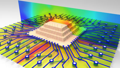
Ansys HFSS 3D enables layout-driven assembly workflows.
Optimizing 5G Antenna Design with HFSS
Using Ansys HFSS, engineers can design phased antenna arrays and optimize antenna properties for end-to-end channel modeling, as well as communication and coupling between individual elements. For example, HFSS 3D Comp Array Technology helps engineers to cut through the complexities of 5G mmWave antenna design with sophisticated solver technology. It’s a multipurpose, full wave 3D electromagnetic (EM) simulation software for designing and simulating high-frequency electronics — from antennas and antenna arrays to radio frequency (RF) or microwave components, high-speed interconnects, filters, connectors, integrated circuit (IC) packages and print circuit boards.
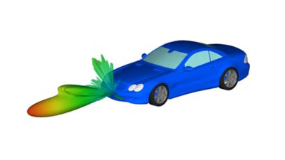
Using HFSS SBR+, engineers can quickly solve electrically large problems associated with 5G antenna design, drawing on its ability to compute installed antenna performance, extended near-field distributions, far-field radiation patterns, antenna-to-antenna coupling, radar cross section, and radar returns from full-scale scenes. HFSS can also be used to accurately answer antenna placement questions through simulation.
“HFSS is an extremely reliable simulation that can zero in on antenna performance for a particular 5G application,” says Larry Williams, Ph.D., a distinguished engineer and thought leader at Ansys. “It has an adaptive process that continuously refines the finite element mesh until it finds a solution that is deterministically accurate. The software also finds its versatility in an SBR+ solver and other solvers, with the ability to address much bigger challenges, like the radiation of an antenna mounted on an aircraft.”
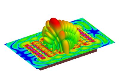
A 3D component arrays simulation
Complex 5G Systems Require Collaboration
Cell phone design is based on input from multiple engineers. Using HFSS supports a more collaborative workflow necessary to address an antenna array functioning within the context of these devices. Consider a 5G cell phone as it communicates to a cell tower. Using continuous signal processing, it is repeatedly adjusting itself to send energy toward that tower. There’s energy to consider, and signal processing involved. Because 5G also applies MIMO, there’s more to control over a multitude of signal paths. Traditionally different teams are assigned to address these issues in antenna design, signal processing and industrial design. It’s a scenario that can often lead to siloed teams struggling to meet deadlines, and track and maintain certification documentation. HFSS helps track and share accurate component design data among engineering groups, resulting in more productive collaboration across workflows.
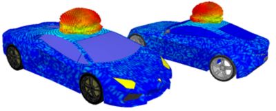
5G supports many innovations, including connected vehicles.
Embedded within a cell phone are multiple antennas, no bigger than the size of a dime integrated into tiny modules, including a radio and a phased array antenna, and some of the analog signal processing hardware. All come together to form a single integrated circuit package to manage these circuit paths. With so many antennas on a single device, figuring out antenna placement becomes very important. Invariably your device not only provides 5G, it also provides 4G with a different band and different antennas, along with Wi-Fi and Bluetooth, all coupling to each other. To address these complexities requires model sharing and design collaboration among teams to successfully simulate and design individual components into high-frequency networks.
HFSS helps you bring these inputs together from start to finish, from the initial import of the chassis from a computer-aided design (CAD) file, to the scripting and automation of that process to clean up the geometry. Using Ansys SpaceClaim, the engineer could then place antennas around that chassis and run simulations, then optimize the design and antenna performance. HFSS simulation software can also be used for coupling beam design to understand how these antennas interact with each other on a single platform, analyze RF signal processing or identify disruptions between antennas as part of a collaborative workflow.
Engineers are using HFSS to solve some of the biggest challenges in 5G antenna design. Read on to learn more about this best-in-class 3D high-frequency electromagnetic simulation software.

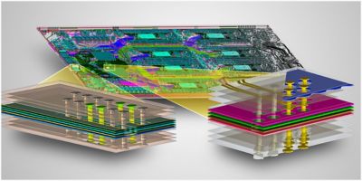
Optimizing speed with Ansys HFSS regions in Ansys SIwave.