Synopsys and Ansys power the future of innovation—connecting silicon to systems.
-
-
Access Free Student Software
Ansys empowers the next generation of engineers
Students get free access to world-class simulation software.
-
Connect with Ansys Now!
Design your future
Connect with Ansys to explore how simulation can power your next breakthrough.
Free Trials
Products & Services
Learn
About
Back
Products & Services
Back
Learn
Ansys empowers the next generation of engineers
Students get free access to world-class simulation software.
Back
About
Design your future
Connect with Ansys to explore how simulation can power your next breakthrough.
Free Trials
TOPIC DETAILS
What is a Turbine?
Turbines convert the energy from a gas or liquid into power by converting a working fluid’s kinetic energy in the form of velocity, and potential energy in the form of pressure, into rotating kinetic energy through multiple turbine blades attached to a shaft. The blade is essentially a lever pushed on by the momentum and pressure of the fluid, and the force on the lever creates torque around the shaft, producing mechanical energy. This energy can then be used by any system attached to the shaft.
The word “turbine” comes from the Latin turbo, meaning “to whirl.” This through-flow approach for pulling energy from a fluid contrasts with piston-based energy extraction machines like an internal combustion engine (ICE) or a steam engine. Devices that use a turbine for power extraction are usually classified as turbomachinery.
Humans have been using turbines to power industrial innovation for millennia, starting with simple water wheels and windmills attached to stone mills. Today, we use turbines to use energy from wind, water, compressed air, steam, and heated gases for electric power; to make our car engines more efficient; to propel aircraft; and much more. The turbomachinery industry focuses on understanding and improving the thermodynamics, fluid dynamics, and robustness of turbines and turbomachinery.
How Turbines Work
All turbines have thin structures that the fluid pushes against or flows around, called blades, that are attached to a cylinder connected to a shaft. However, turbines are classified differently depending on whether they pull energy from the momentum of a fluid (impulse turbines) or if they use the pressure of the fluid (reaction turbines).
Impulse Turbines
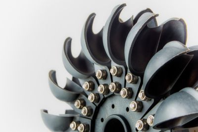
A Pelton water turbine, one of the more common types of impulse turbines
In an impulse turbine, a stream of fluid strikes series of blades that resemble paddles or buckets. The kinetic energy of the fluid stream is converted into mechanical energy as it moves the blades. This generates force that produces torque on the shaft and spins the rotor.
The earliest form of an impulse turbine was a water wheel, in which the paddles on a wheel were moved by the current of a river or canal. In modern impulse turbines, nozzles create a high-velocity stream of water, steam, or compressed air. Unlike reaction turbines, impulse turbines do not need an enclosure to guide the fluid. In an impulse turbine system, the pressure of the fluid doesn’t change after it exits the nozzle, and the fluid’s flow direction is often altered significantly after impacting the blades on the turbine.
Reaction Turbines
Reaction turbines work by channeling a fluid through a set of blades that expand the fluid, converting pressure into force on the blades. Each blade receives the same load. A reaction turbine can have multiple sets of rotors, called stages, that are optimized for the pressure in that part of the fluid flow.
The most visible types of reaction turbines are wind turbines and gas turbines used for jet engines. Most steam turbines and natural gas power turbines are reaction turbines. Reaction turbines use a shroud or case to position the fluid flow through the turbine blades. The flow in reaction turbines undergoes a significant pressure drop as the fluid moves through the turbine.
Key Components in Turbines
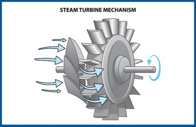
The key components of a steam turbine. Steam enters and is directed to the rotor by the stators. The pressure and velocity of the steam are converted into force on the blades, which in turn creates torque on the shaft.
A good way to understand how turbines work is to look at what each key component does.
Turbine Blades
The most crucial components of a turbine are the blades. These are attached to a shaft via a platform, usually a disk. Turbine blades are sometimes called rotor blades. The purpose of a turbine blade is to convert momentum or pressure drop into a force acting perpendicular to the axis of rotation, thus creating torque around the shaft.
Turbine blades can be as simple as flat paddles that dip into a flowing channel of water, angled perpendicular to the flow direction. They can also be as complex as a radial turbine in a turbocharger arranged in a helix pattern to convert flow from the circumference of the rotor inward to axial flow that is aligned with the shaft. Some blades are very thin and tall, as in a steam turbine or a wind turbine. Others are longer and relatively thick, as in the high-pressure blades in gas turbine engines.
Turbine Rotor
The wheel, disk, or drum that turbine blades attach to is called a turbine rotor.
Shaft
The mechanical power produced by the turbine blades and transferred by the turbine rotor is transmitted out of the turbine by a shaft. The shaft is connected to the static structure through high-speed bearings. Multiple turbine rotors can be attached to the same shaft. The shaft is connected to whatever system the turbine powers, often through a gearbox.
Gearbox
The rotational velocity or torque of the shaft may not match a turbine's application. A gearbox is often added to a turbine to raise or lower the rotation speed of the turbine and inversely lower or raise the torque.
Turbine Rotor Assembly
The turbine rotor assembly is the rotating portion of a turbine consisting of the turbine rotor, shaft, and turbine blades. The three components can each be separated and assembled through various mechanisms, or the constituent components can be fabricated from a single piece of material.
Rotating Group
A rotating group is a collection of turbine rotor assemblies spinning at the same speed. Most gas turbines have a multistage high-pressure rotating group that powers a compressor and a low-pressure rotating group that powers the propulsion fan or power shaft. In a steam turbine, multiple stages are used to extract pressure as the energy in the steam decreases.
Stator Blades or Vanes
The velocity, magnitude, and direction, as well as the pressure of fluid flow in and out of a turbine rotor assembly, are critical to turbine performance. Turbines use stationary blades upstream and downstream of the rotor assembly to control pressure, axial velocity, and tangential velocity or swirl. These nonrotating blades are called stator blades or vanes.
Turbine Stage
A turbine stage refers to a single rotor assembly and its supporting static components, including the stator it is paired with. Many turbines have multiple stages in their turbine section and often have two or more turbine sections, each optimized for a specific pressure drop.
Nozzle
A nozzle converts pressure into velocity and directs the flow as a cylindrical stream at the optimal angle. In reaction turbines, vanes that convert pressure into velocity are often called nozzles.
Bearings
One critical component of any turbine are the bearings that allow the rotor assembly to rotate relative to the stationary portions of the system. The speed, temperature, operating environment, and loads of a turbine determine which type and what size of bearing are needed.
Shroud or Turbine Case
Most reaction turbines require a solid surface on the outer diameter of the turbine rotor assembly to force the fluid through the blades. This outer shell is called a shroud or turbine case. The turbine case is usually part of the stationary structure of a turbine. In the case of a shrouded turbine rotor, a band of material is added to the outside diameter of the rotor assembly.
Inlet
An inlet is the area where the fluid enters the turbine. The inlet is shaped to obtain the optimal pressure and velocity for the turbine. Movable vanes or valves are often placed in inlets to control flow into the turbine.
Outlet
The working fluid exits the turbine through the outlet. Engineers also optimize the outlet’s shape to improve performance.
Static Structure
The nonrotating parts of a turbine. The static structure contains the inlet outlet, mounts, cooling hardware, structures to hold the bearings, and a housing or case to keep the flow inside the turbine and foreign objects out of the flow.
Instrumentation and Control System
A critical part of any turbine is the mechanical and electronic controls and sensors that measure physical properties in the turbine. Usually part of the control system for the entire turbomachine, they are used to modify inputs to the turbine for optimal turbine efficiency, performance, and safety.
Types of Turbines and Their Applications
There are many different ways to categorize turbines. These classifications refer to the rotating machinery that converts the energy in a moving fluid into useful work, not the whole turbomachinery system or external devices the turbine powers.
Some common ways to specify the type of turbine used in a piece of turbomachinery include:
- Working fluid: Turbines can convert energy from water, wind, steam, heated gases, or compressed air.
- Flow direction: Axial flow is aligned with the shaft, tangential flow is perpendicular to the shaft, and radial flow is inward from the outside diameter toward the shaft. Some turbines involve a mixed flow, with both radial flow at the inlet and axial flow at the outlet.
- Velocity or pressure energy extraction: As mentioned above, impulse turbines use velocity against a blade to create a force, and reaction turbines use pressure.
Common Types and Applications of Turbomachinery
It is difficult to talk about turbines without defining the type of machinery they power. Below is a list of the most common types of turbomachinery, the energy source for the working fluids they use, and some well-known applications for each.
Water Turbines or Hydraulic Turbines
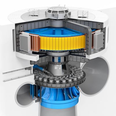
An illustration of a large hydroelectric power generation system. The single-stage turbine is the blue structure on the bottom. Variable-angle stators direct the flow into the outside diameter of the rotor, and energy is extracted as the water is deflected downward. The yellow and blue structure on top is the electric generator.
The oldest type of turbomachinery is water or hydraulic turbines. The working fluid is water, and the water's energy source is gravity. When used for energy generation in dams, hydroelectric power turbines are usually mixed-flow designs directly connected to a generator at the base of the dam. Power generation is the most common application for hydraulic turbines.
Steam Turbines
Most power plants around the world use steam turbines to produce electricity. Heat is added to water to cause a phase change, capturing significant energy. The source of that thermal energy is usually the combustion of fossil fuels, but it can also come from a nuclear reactor. A growing form of renewable energy uses concentrated solar power to boil water for steam turbines in large power plants.
Wind Turbines
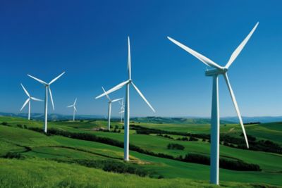
A collection of wind turbines is often referred to as a wind farm. They are often constructed in rural areas or offshore.
Humans developed windmills, and later wind turbines, to harness wind power as a replacement for human and animal labor. Solar heating in the atmosphere is the energy source for wind. Modern wind energy systems use large, highly efficient three-blade wind turbines gathered on land or offshore wind farms. The vast majority of large wind turbines, like the one shown in the photo above, are horizontal-axis wind turbines. Smaller vertical-axis wind turbines are sometimes used in more urban settings. Although some parts of the world still use wind power to turn mills and pump water, power generation is the primary use for wind turbines today.
Air Turbines
High-performance hand tools are often directly driven by compressed air. Energy is added to the air by a piston and stored in a pressure vessel. A valve releases the high-pressure air to impinge on an impulse turbine, usually a Pelton wheel, to create very high rotational speeds. The most common form of an air turbine is a dental drill.
Gas Turbines or Turbine Engines
Gas turbines, or combustion turbines, are a large family of turbomachinery that uses a combustion chamber to add energy to a gas that then expands through a turbine. Turbines that provide propulsion are called turbine engines. Gas turbines usually also include a compressor driven by a rotating group in the turbine section that improves combustion efficiency. Gas turbine classifications include the type of combustion they use or how their power output is used.
- Power turbines: These are gas turbines, usually powered by natural gas, that power generators for electrical power generation to provide electrical power rather than propulsion.
- Turbochargers: A turbine extracts otherwise-unused energy from combustion in an internal combustion engine to power a compressor upstream of the cylinders, making the combustion more powerful.
- Turbojets: Turbojet engines produce thrust for aircraft from combustion only and have a single rotating group that, like a turbocharger, drives a compressor, increasing combustion efficiency.
- Turbofans: Turbofan engines have a second rotating group that drives a large fan, an efficient shrouded propeller, that is the primary source of thrust. They are more efficient than turbojet engines and are the primary form of commercial aircraft propulsion today.
- Turboshafts: Instead of producing thrust for propulsion, turboshaft engines produce torque to run a propeller for aircraft, a screw for watercraft, or wheels for land vehicles.
- Turbopumps: Turbopumps use hot gases from combustion to drive pumps. The most common types of turbopump are fuel pumps for liquid-fueled rocket engines or high-flow-rate pumps for oil and gas extraction.
Designing and Improving Turbines with Simulation
Engineers working on turbine designs look at different aspects of defining and optimizing a turbine. People used trial and error, then simple equations to develop blade geometry, inlet configuration, and rotor designs in early turbines. But as the demand for more efficient, less costly turbines grew, engineers turned to advanced simulation to drive their designs.
As with all designs, turbine design is a balance between cost, efficiency, performance, and robustness. For turbines used in aircraft propulsion, engineers also need to consider weight.
Flow Path Design
The basic configuration of a turbine is laid out in the flow path design phase. Performance engineers look at the thermodynamic behavior of a turbine in the context of the entire turbomachinery system it is powering. They may use a 2D throughflow tool like Ansys Vista TF turbomachinery design software to try different types of flows, stage configurations, stator options, and inlet and outlet geometry.
Blade and Stator Design
Once a flow path is defined, the next step is to design the turbine blades and stators that belong to each stage. Basic calculations called vector diagrams can give engineers a first guess. Next, they need to create 3D geometry and use a general-purpose computational fluid dynamics (CFD) tool like Ansys Fluent fluid simulation software or a turbomachinery-focused CFD platform like Ansys CFX software. Engineers use tools like these to guide them in refining 3D geometry to optimize energy extraction from a fluid flow under multiple operating conditions. Blade design is an iterative process that is refined over time.
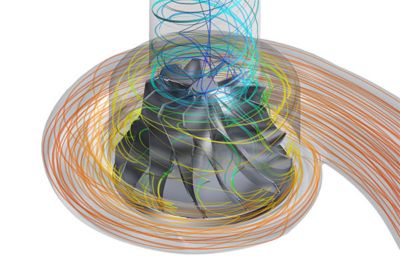
A CFD simulation of a radial flow turbine used in a turbocharger. Hot exhaust gases enter from the outside diameter, energy is extracted, and the flow leaves the turbine along the shaft axis.
Multistage and Transient Component Design
Once the blade designs are completed, the next step is to optimize how the static and rotating stages work together. The blade and stator angles of each stage are modified so engineers can examine the static and transient flow over time using the advanced capabilities of turbomachinery-specific tool like CFX software or Fluent software, which can model both stationary and rotating regions.
Structural and Thermal Design
Designing both the rotating and static portions of a turbine is challenging and complex due to the extreme loading conditions and cyclic nature of those high loads. The high temperatures in gas and steam turbines also present their own challenges, as do vibrations induced by the cyclical pressure and rotational loads that turbines encounter. Most thermal and mechanical engineers involved in turbine design turn to a general-purpose multiphysics simulation tool like Ansys Mechanical structural finite element analysis (FEA) software to capture the static, dynamic, and vibration behavior of each component and assembly in a turbine. This includes simulating bearings, secondary cooling, rotor dynamics, disk stresses, blade stresses, durability, and thermal stresses. Engineers can also couple a CFD tool like CFX software to a structural program like Mechanical software to understand the vibration interaction between the fluid and structural domains.
System Design
Engineers also need to design turbines in the context of the entire system they belong to. Once the system is mapped out, engineers use a model-based systems engineering (MBSE) tool like Ansys ModelCenter software to ensure that each component is optimized systemwide.
Explore the Ansys Fluids product collection to learn more.
Related Resources
Let’s Get Started
If you're facing engineering challenges, our team is here to assist. With a wealth of experience and a commitment to innovation, we invite you to reach out to us. Let's collaborate to turn your engineering obstacles into opportunities for growth and success. Contact us today to start the conversation.