Synopsys and Ansys power the future of innovation—connecting silicon to systems.
-
-
Access Free Student Software
Ansys empowers the next generation of engineers
Students get free access to world-class simulation software.
-
Connect with Ansys Now!
Design your future
Connect with Ansys to explore how simulation can power your next breakthrough.
Free Trials
Products & Services
Learn
About
Back
Products & Services
Back
Learn
Ansys empowers the next generation of engineers
Students get free access to world-class simulation software.
Back
About
Design your future
Connect with Ansys to explore how simulation can power your next breakthrough.
Free Trials

Jet engine turbine blades are required to operate in some of the most extreme conditions, where operating temperatures may exceed the melting point of the alloys used. As a result, complex cooling geometries, coatings, and other properties are used to keep blades within operational temperature, with failure not being an option. However, manufactured parts may contain small embedded and hidden defects, creating a need to use a methodology such as CT inspection to inspect the inside of these parts.
CT inspection is a nondestructive industrial x-ray process, where a part is rotated 360 degrees while hundreds or thousands of individual 2D radiographs are captured at specific degree intervals. The collection of 2D radiographs are then reconstructed into a 3D CT volume which can be digitally sliced through at any angle, allowing users to inspect both the external and internal features of the product without needing to physically cut or open it.
However, one challenge with this workflow is that the ability to resolve defects and dimensions within the part is dictated by overall image quality and image quality can be directly correlated with inspection cycle time. High density and complex parts, like turbine blades, typically require a significant amount of scan and technician interpretation time. This can create a potential bottleneck for high-throughput applications.
Ansys Simpleware software offers a solution to the challenge of bottlenecks in manual image review through case-specific analysis with artificial intelligence (AI)-enabled machine learning (ML) methods. With this approach, time-consuming manual segmentation time is eliminated from the work, and inspection time is reduced by the pre-determination of defect locations. Further scaling up of inspection is therefore only dependent on the power of the hardware being used for the inspection. In collaboration with Avonix Imaging, a project was developed to detect low-frequency critical defects in high-pressure turbine blades, with the goal of creating a fully automated inspection assistant to highlight possible defect regions, and to speed up critical inspection workflows.
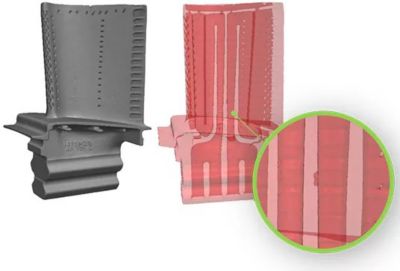
Automated critical defect inspection tool in Simpleware software
Obtaining Input Data
X-ray CT technology has seen a lot of great innovation in recent years. Expanded capabilities through scanning methods like Pixel Push, helical CT, offset CT, and even hardware improvements including heat dissipating rotating targets and 450kV microfocus tubes have been instrumental in the growth of CT scanning across many industries. Oftentimes, CT can provide a view that users cannot obtain any other way.
Deciding which CT method and technique is best is largely dependent on the specific needs of each company and the goals of their project. CT technicians need to consider a product’s material, density, size, shape, features, as well as defect size requirements, scan time goals, and even the desired output format, as all these details can have an impact on the optimum CT scanning technique.
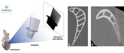
Illustration of X-ray process: high-resolution LDA scan (a) and a slice from a high-speed DDA scan (b)
Once goals and product details are understood, a scan technique can be developed. The most common hardware parameters used with industrial CT are X-ray energy (225kV or 450kV), focal spot size (mini-focus or micro-focus), and detector type (LDA or DDA). From there, part fixturing, geometric magnification, and manipulator positioning (source to part, source to detector, etc.) are set. Finally, acquisition methods, number of projections, and other fine-tuning adjustments are made before running the CT scan.
As for this project, due to the high density of turbine blades, 450kV micro-focus tube was selected and both an LDA and DDA detector was tested. To develop an ideal reference scan, Avonix Imaging performed a number of high-quality LDA scans as well as a sample of high-speed scans using a DDA detector on the same set of turbine blade samples. Scan times during these sample runs ranged from a few minutes to many hours, therefore illustrating the importance of understanding project goals and finding a technique that meets those goals as efficiently as possible.
Running an Automated Workflow
Once the CT scanning process is optimized for efficiency, the next step is to develop an automated inspection workflow.
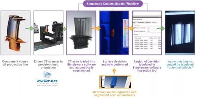
Automated inspection workflow using Simpleware software
In practice, the automated workflow involves:
- A component coming off the production line
- Entering a CT scanner in a predetermined orientation for inspection-speed scanning, typically next to a production line
- Loading the CT scan into Simpleware software and running the Simpleware AI-enabled workflow:
- The CT scan is automatically segmented into regions of interest based on training data from an expert user
- Surface deviation analysis is carried out, whereby the “ideal” reference model is registered with segmented scans automatically
- The region of deviation between the two models is tabulated using an inspection tool, with sensitivity able to be adjusted depending on the defects being examined
- Carrying out inspection using tabulated "potential defects"
This customized automated workflow is designed to allow rapid defect defection for high-volume manufacturing, reducing the need for time-intensive manual segmentation.
Future Impact
The automated workflow developed with data from Avonix Imaging demonstrates the potential to solve bottlenecks associated with inspection for high-value parts such as jet engine blades. In addition, the methods used in Simpleware software can be easily extended through 'bolt-on' additional measurement strategies for further analysis. Example measurements include GD&T-style measurements, wall thickness, and centerline cross-section analysis. This method aims to aid inspectors by providing augmented data including preliminary locations of interest to evaluate, which can ease the inspection process and reduce overall inspection time, creating more efficient production lines for manufacturers.
Learn more about Ansys Simpleware software.


The Advantage Blog
The Ansys Advantage blog, featuring contributions from Ansys and other technology experts, keeps you updated on how Ansys simulation is powering innovation that drives human advancement.