-
-
Access Free Student Software
Ansys empowers the next generation of engineers
Students get free access to world-class simulation software.
-
Connect with Ansys Now!
Design your future
Connect with Ansys to explore how simulation can power your next breakthrough.
Free Trials
Products & Services
Learn
About
Back
Products & Services
Back
Learn
Ansys empowers the next generation of engineers
Students get free access to world-class simulation software.
Back
About
Design your future
Connect with Ansys to explore how simulation can power your next breakthrough.
Free Trials
ANSYS BLOG
April 22, 2021
Struggling With PCB Modeling? Try Trace Reinforcements
Printed circuit boards (PCBs) exist in some form in nearly every piece of electronic equipment in the world and they perform two major functions:
1) Structural: PCBs hold all of the electronic components in place, e.g., the capacitors, resistors, integrated circuits (ICs) and more.
2) Electrical: PCBs provide the electrical interconnection between the components.
Because they perform the vital function of structurally holding electronic components in place and electrically connecting those components, ensuring PCB assembly reliability is critical to the success of a product. Through simulation, PCBs can be modeled and tested for specific stressors and use-environments to determine failure risks before physical prototyping. A recent methodology with the potential to significantly improve PCB model fidelity at the board level is Ansys’ trace reinforcement workflow.
Let’s discuss the major advantages of this methodology via a complete trace reinforcements workflow that you can implement into your own design process.
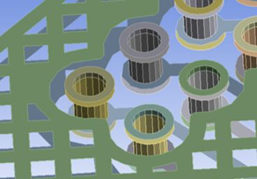
Trace reinforcements are represented by copper features using shell and beam reinforcement elements
What Are Trace Reinforcements?
As PCBs become increasingly complex, (PCBs with flex and rigid-flex circuits, high-density interconnects, buried vias and micro vias), and as components get smaller, it becomes more difficult to simulate PCBs accurately. It may no longer be appropriate to approximate boards with homogenous properties, a common strategy in structural finite element analysis (FEA) modeling.
Trace reinforcements have emerged as a possible solution to capture these complex details, while still running full board-level simulations that are manageable in scope and time.
Watch the “How to Use Trace Reinforcements to Optimize PCB Models” webinar below to learn more.
Traces are the copper connections that electrically connect different components and leads on a PCB.
The trace reinforcement methodology treats the copper traces in a PCB as 1 or 2D reinforcing features within 3D structural resin base elements.
Material reinforcements are widely used in many industries to improve structural properties, such as steel rebar reinforced concrete, carbon fiber reinforced polymers for aircraft rudders and nylon strands in tires. Ansys’ FEA software uses specialized reinforcement elements to model the reinforcement effects of such materials.
Ansys’ trace reinforcement workflow extends these reinforcement elements that are commonly used in other industries to approximate the properties of PCBs, treating the copper traces as the reinforcements and the resin/laminate (which actually holds together the traces in a PCB) as the base that is reinforced.
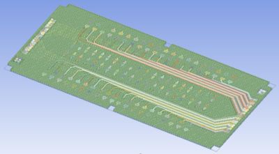
The Ansys Trace Reinforcement Workflow
Ansys has developed a comprehensive workflow that uses the smeared reinforcement approach to directly account for all trace geometry within a PCB. Each layer of the PCB is modeled with solid base elements, and the traces, modeled with 2D shells and beams, act as reinforcing elements. This way, you can include all of the detailed trace geometry, but it is much easier to mesh and simulate because you are not trying to model these as 3D bodies with connections.
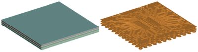
3D Base Geometry (Left) and Associated 2D Trace Reinforcement Geometry (Right)
One useful application of the trace reinforcement approach is thermal mechanical analysis, which can be used to analyze how trace geometry can affect localized deflection during reflow. When components are soldered, the PCB can expand non-uniformly due to features like buried vias. Using the trace reinforcements methodology, design engineers can determine potential defects and test different design changes for optimization.
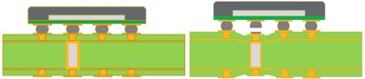
Illustration showing localized board surface deformation resulting in a soldering defect - a potential issue during reflow.
In the video below, Ansys Senior Application Engineer Salmon Kalkhoran explains our trace reinforcement workflow using Ansys Sherlock, Ansys Workbench, Ansys SpaceClaim and Ansys Mechanical.
Interested in trying out the workflow for yourself? Request a demo.