Synopsys and Ansys power the future of innovation—connecting silicon to systems.
-
-
Access Free Student Software
Ansys empowers the next generation of engineers
Students get free access to world-class simulation software.
-
Connect with Ansys Now!
Design your future
Connect with Ansys to explore how simulation can power your next breakthrough.
Free Trials
Products & Services
Learn
About
Back
Products & Services
Back
Learn
Ansys empowers the next generation of engineers
Students get free access to world-class simulation software.
Back
About
Design your future
Connect with Ansys to explore how simulation can power your next breakthrough.
Free Trials
ANSYS BLOG
July 16, 2021
New HFSS SBR+ Technology in Ansys 2021 R2 a Big Step Forward for Automotive Radar Integration
Radar is a key technology for autonomous vehicles and advanced driver assistance systems (ADAS). Radar technology requires antennas to transmit and receive electromagnetic waves. Where an antenna is placed significantly alters its radiation characteristics. The behavior of an antenna suspended in free space during testing can drastically change when it is placed near the dielectrics and conductors in the real world.
In automotive radar, for example, the radar sensor is often placed behind the fascia or vehicle emblem for aesthetics and protective purposes. Figure 1 shows a radar antenna, mounted on a metallic bracket behind the emblem of a vehicle. A dielectric radome with non-uniform thickness covers the antenna.
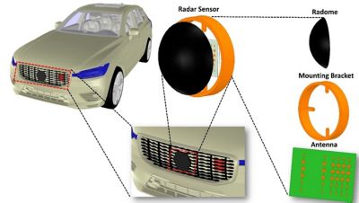
Figure1: Placement of radar antennas behind the emblem of a vehicle. The radome has a non-uniform thickness dielectric.
Engineers need to ensure that the bumper and fascia do not significantly reduce the intended gain of the antenna or distort the phase relationships among antenna elements. These effects can reduce the effective detection range of the radar or introduce errors in determining the angle of arrival of targets. Using simulation, engineers can predict the effects of the fascia and bumper on the antenna by including the antenna, bumper and fascia portions in the simulation. However, these simulations are usually electrically large and so require a lot of computational power and memory to solve using conventional techniques like the finite element method (FEM).
Solve Electrically Large Problems Quickly
The Ansys HFSS Shooting and Bouncing Rays (SBR+) solver is an asymptotic, ray tracing electromagnetic solver that efficiently solves electrically large problems. HFSS SBR+ is a hybridization of geometrical optics (GO) and physical optics (PO). Specifically, HFSS SBR+ uses GO to extend PO to multiple bounces while also accounting for additional physics. HFSS SBR+ also applies the physical theory of diffraction (PTD) wedge correction and creeping waves (CW) to account for the distortion of surface currents near abrupt surface discontinuities and current propagation beyond curved-surface shadow boundaries. The uniform theory of diffraction (UTD) is used to augment GO rays and to extend PTD to multiple bounces, thus allowing illumination of CAD surfaces in the shadow region of the transmitter according to GO.
Accurately Answer Antenna Placement Questions
Traditional shooting and bouncing ray techniques require geometries be introduced to the solver as surfaces characterized by Fresnel reflection and transmission coefficients. These coefficients are in tables that are either computed internally or provided by the user. For example, when a conducting material is assigned to the volume of an object, its volume is internally converted into a series of faces with a single-sided, finite conductivity boundary condition. With this approach, bulk materials cannot be assigned to dielectrics. Instead, dielectrics are described by an impedance boundary condition that includes the effect of uniform finite thickness. This means that dielectrics can only be simulated as uniform-thickness coatings or slabs.
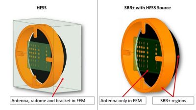
Figure 2: Alternative simulation workflows for evaluating impact of platforms on the radiation characteristics of an antenna. In the SBR+ approach, the radome is a volumetric dielectric SBR+ region.
Starting with HFSS 2021 R2, it’s possible to assign non-conductive dielectric materials to volume SBR+ (vSBR+) regions. Rays are allowed to propagate inside the dielectric region according to Snell’s law of reflection and refraction. This new feature makes it possible to accurately solve problems involving dielectric regions of variable thickness, such as car fasciae, bumpers, radomes and lenses.
HFSS evaluates the impact of the radome and bracket on the antenna performance in two ways. In the first approach — full-wave simulation — the antenna, bracket and radome are all placed within the same domain and solved using the HFSS FEM solver. In the second approach, only the antenna is solved with HFSS FEM. The interaction of the antenna with the radome and bracket is determined by assigning SBR+ regions to the radome and bracket. These simulation workflows are shown in Figure 2.
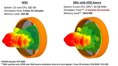
Figure 3: Comparison between the far-field gain patterns obtained from the setups in Figure 2.
With the new vSBR+ for dielectrics, engineers can now accurately simulate dielectric objects with non-uniform thicknesses. Figure 3 shows a comparison between the far-field gain patterns obtained using HFSS FEM and HFSS SBR+. From Figure 3, the HFSS SBR+ results approach the gold-standard accuracy of HFSS FEM while using significantly less memory and time to solve the same problem. The new vSBR+ feature for dielectrics enables engineers to accurately simulate electrically large problems with arbitrarily shaped dielectrics in a fast and efficient manner.
To learn more about this and other new features in HFSS 2021 R2, view the on-demand webinar: Ansys 2021 R2: Ansys HFSS Update.