
ANSYS BLOG
November 3, 2023
The Difference Between MOM, MIM, and MOS Capacitors
At the most basic level, all capacitors store energy via electrical conductors (plates) separated by a dielectric (insulating) material. When one plate receives a positive charge and the other plate receives a negative charge, the capacitor is holding a charge. There are many types of capacitors with many different uses — from storing computer memory in digital circuits, to filtering noise from electronic signals, to protecting one part of a circuit from the effects of another, and more.
Let's take a look at three common types of analog integrated circuit capacitors: metal-oxide-metal, metal-insulator-metal, and metal-oxide-semiconductor capacitors.
What is a Metal-Oxide-Metal (MOM) Capacitor?
Metal-oxide-metal (MOM) capacitors are small and versatile devices used in chips. They are interdigitated (interlocking like the fingers of two clasped hands), multi-finger capacitors formed by metal layers. The standard metal wiring lines (and optionally vias — the plated through holes on a wired board) are used to create the plates of the capacitor, and the lateral (intralayer) capacitive coupling effect between plates produces the required capacitance.
This lateral capacitive coupling offers superior matching characteristics compared to vertical coupling, mainly due to the enhanced process control of lateral dimensions as opposed to metal and dielectric layer thicknesses. To increase capacitance density, multiple metal layers can be connected in parallel using vias, forming a vertical metal wall or mesh. Typically, the lowest metal layers (such as M1–M5) with the smallest metal line width and spacing are employed in MOM capacitors to maximize capacitance density.

Metal-oxide-metal capacitor structure
Advantages of Metal-Oxide-Metal Capacitors
- Low cost
- High capacitance density
- Excellent radio frequency (RF) characteristics
- Excellent matching characteristics
- No additional mask layers
- Symmetrical plane structure
Disadvantages of Metal-Oxide-Metal Capacitors
- Moderate bottom plate parasitics
- Low density
- Higher series inductance and resistance
- Low breakdown voltage
Applications of Metal-Oxide-Metal Capacitors
- High-speed integrated circuits (IC)
- Microelectronics
- RF and analog applications
- Oscillator circuits
What is a Metal-Insulator-Metal (MIM) Capacitor?
Metal-insulator-metal (MIM) capacitors are another class of compact capacitors with distinct advantages. They are like a parallel plate capacitor, in which metal plates (electrodes) are separated by an insulating material (dielectric). These capacitors are widely used because they exhibit high capacitance per unit area. To further enhance the capacitance value, MIM capacitors are typically constructed using three plates, two metal layers from the standard fabrication process (which often are the topmost layers), and a special metal layer in the middle. This unique arrangement allows MIM capacitors to achieve higher capacitance density while maintaining the advantages of stable performance and low leakage associated with their insulating dielectric material.
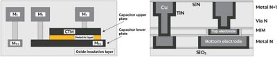
Metal-insulator-metal capacitor structure
Advantages of metal-insulator-metal capacitors
- Stable capacitance
- High capacitance per unit area
- Good quality factor
- Good linearity
Disadvantages of metal-insulator-metal capacitors
- Special process required to create masking layers
- Increased cost
Applications of metal-insulator-metal capacitors
- Integrated circuits (ICs)
- Memory modules
- RF and microwave devices
- Photodetectors
What is a Metal-Oxide-Semiconductor (MOS) Capacitor?
Metal-oxide-semiconductor (MOS) capacitors are essentially a transistor that is used as a capacitor, in which the gate is the top plate of the capacitor, the drain and source connection make up the bottom plate, and the thin oxide layer from the gate is the insulator layer. The MOS capacitor is not a widely used device in and of itself. However, it is part of the MOS transistor (metal-oxide semiconductor field-effect transistor, or MOSFET).
The capacitance value of MOS capacitors depends on the DC voltage applied at the gate. The varying voltage changes the depletion areas at the gate, altering the dielectric properties and subsequently modifying the capacitance. MOS capacitors are particularly useful for local supply decoupling applications, in which the DC voltage remains constant.
Advantages of metal-oxide-semiconductor capacitors
- Exhibits higher capacitance per unit area compared to MIM capacitors
- Has a thinner insulator (SiO2) at the gate
Disadvantages of metal-oxide-semiconductor capacitors
- Significant variation in capacitance, with voltage limiting usage
- Parasitic resistance from the bottom plate impacts performance
Applications of metal-oxide-semiconductor capacitors
- ICs
- Analog circuits
- Voltage reference circuits
- Tunable filters
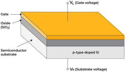
P-type semiconductor metal-oxide-semiconductor capacitor
MOM, MIM, and MOS Comparison
Property | MOM | MIM | MOS |
Structure | Same-layer interdigitated structure with oxide dielectric layer | Two or more metal plates separated by an insulating material (e.g., silicon nitride, tantalum pentoxide). | Metal gate electrode, oxide insulator layer, and semiconductor substrate |
Dielectric material | Metal oxides (e.g., SiO2, Al2O3) | Insulators (e.g., Si3N4 or Ta2O5) | Insulator (SiO2) |
Capacitance density | High | Moderate to high | Moderate to high |
Capacitance variation with voltage | Low | Low | High |
Sensitivity to temperature | Slightly sensitive | Moderately sensitive | Slightly sensitive |
Fabrication process | Relatively simple | More complex | Standard process |
Parasitics | High | Low | High (mainly at the bottom plate) |
Applications | Integrated circuits, microelectronics, analog and RF circuits | Integrated circuits, memory modules, analog and RF circuits | Integrated circuits, MOSFETs, sensors, analog applications |
Capacitance Extraction Using Simulation
MOM capacitors are complex structures that are considerably large and consist of many super-thin fingers. These are highly susceptible to distortion caused by layout-dependent effects (LDE). Consequently, it is crucial to model LDE with precision to ensure the calculation of an accurate model for MOM capacitors. Modeling MOM capacitors in the context of the overall layout can enable designers to predict the capacitive coupling between them and the rest of the circuit, which is critical for sensitive applications. However, achieving this level of accuracy is not always feasible using traditional electromagnetic (EM) solvers. As a result, designers often opt to treat MOM capacitors as discrete components and directly connect their models to the test bench.
Fabricating MIM capacitors poses a greater challenge as it requires additional mask layers during the fabrication process. Specific MIM layers are introduced in the tech file to define and design MIM capacitors. Modeling the complete MIM structure in the context of the full layout is essential to predict capacitance accuracy.
MOM and MIM capacitors are widely used in ICs, especially for RF and analog applications. It’s critical to accurately model these capacitors for capacitance accuracy and matching requirements with respect to layout using simulation software. Ansys RaptorH provides the capability to extract electromagnetic models for all passive components and arbitrary routing of layouts that are mature or are still in progress. Components may be planes (solid or perforated), transmission lines, spiral inductors, and MIM/MoM capacitors, which can be extracted together with high-speed/high-frequency routing to calculate a fully coupled electromagnetic model. This includes the added benefit of automation, which enables a very simple and fast setup of the electromagnetic extraction run.
For a successful IC design, it’s critical to model these capacitors with high accuracy using advanced simulation software. Learn more about Ansys RaptorH.
See What Ansys Can Do For You
See What Ansys Can Do For You
Contact Us
Contact us today