

ANSYS ADVANTAGE MAGAZINE
DATE: 2018
5G Antenna Technology for Smart Products
Eric Black, Chief Technology Officer, Pivotal Commware

The dramatic rise of smart, connected products requires a rapidly increasing communications bandwidth, but the radio frequency spectrum available is growing at a much slower pace than what is needed. One way the fifth generation of cellular wireless technology, 5G, can address this problem is by leveraging beamforming antennas to send different signals to different areas of the cellular network, enabling multiple simultaneous transmissions at the same time on the same frequency. Pivotal Commware is designing the next generation of these beamforming antennas or cellular base stations and other applications, at a fraction of the cost of existing methods. The company’s engineers use Ansys HFSS to create antenna designs that meet design requirements on the first or second pass, substantially reducing the time required to bring new antennas to market in this highly competitive industry.
"Cost, size, weight and power (C-SWaP) are critical challenges in communication system design."
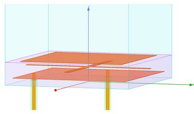
Floquet analysis generates infinite arrays from a single antenna element.
Previous 3G and 4G LTE cellular technology perfected the process of dividing frequency bands into ever-narrower segments and splitting time into smaller and smaller pulses to increase the number of mobile phone users that can be accommodated by the network. Pivotal Commware addresses 5G’s new focus on subdividing space with Pivotal’s holographic beamforming (HBF) antenna technology. HBF uses varactors, electronic components that are far simpler and less expensive than the complex electronics used in existing beamforming antennas such as phased arrays or multiple-input multiple-output (MIMO).
Cost, size, weight and power (C-SWaP) are critical challenges in communication system design. Using the traditional approach of building a prototype over the course of a month — determining any flaws, creating a new design and so on — it would be impossible to meet product launch schedules. Instead, Pivotal engineers use Ansys HFSS, obtained through the Ansys Startup Program, to design all key components of its 5G antennas — transitions, feed networks, couplers, RF/DC blocks, transmission lines and radiating elements. Ansys simulation tools enable Pivotal’s holographic beamforming technology to overcome the C-SWaP challenge. Leveraging simulation, engineers obtain a reliable design early in the development process and avoid multiple prototype iterations required by traditional design methods.
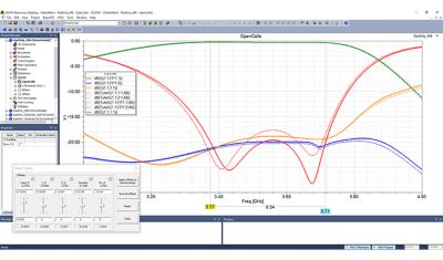
Derivative tuning allows fine adjustments without the need for additional simulation runs.
BEAMFORMING KEY TO 5G PERFORMANCE
In 4G LTE, cellular technology has reached the theoretical limits of time and frequency multiplexing, so engineers are looking at using software-driven, highly directional antennas to slice up physical space. This will enable mobile phone users in different locations within a cellular network to share the same frequency simultaneously. A leading technology in this space is MIMO, which uses many transmitters and receivers to excite the various elements in each antenna to transmit data streams that can later combine despite traveling different paths. However, MIMO requires a complex and costly baseband unit (BBU) to coordinate the system and radios behind every element, which results in high cost and power consumption.
Holographic beamforming, on the other hand, uses a single varactor (variable capacitors whose capacitance depends on DC bias) per antenna element to direct wireless capacity wherever it is needed within the cell without the need for multiple radios or a complex BBU. This technology is called holographic because a pattern of varactor bias states in the antenna control radio frequency waves in the same way that holograms control light waves to produce a 3D image. Altering the DC bias of the varactors changes the impedance seen by the reference wave at each element, thus changing the radiation pattern of the array and directing the beam at a cluster of mobile phone users, or even a single mobile phone user, within the cellular network. All components used in the construction of holographic beamforming antennas are high-volume, low-cost and off-the-shelf, resulting in a much lower cost than MIMO or phased arrays.
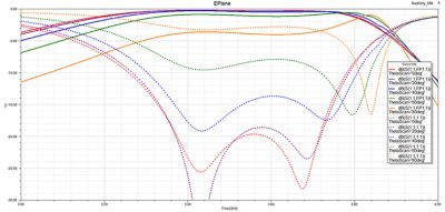
A parametric study identifies roll-off as a function of degrees from centerline of antenna.
"Pivotal Commware addresses 5G’s new focus on subdividing space with antennas based on holographic beamforming technology."
RADIATORS PRESENT DESIGN CHALLENGE
Pivotal Commware engineers use Ansys HFSS to model all microwave components of the HBF antenna. Of particular importance are the element radiators, passive elements of the antenna responsible for the radiation pattern. Radiators present a particular design challenge because they must achieve efficiency over a wide range of frequencies in a compact form factor, smaller than one-fifth of a wavelength.
An example element radiator has a dual-polarized second-order response and is modeled with master/slave boundaries on the sidewalls, two coaxial feeds through an ideal ground plane at z=0, and a Floquet port on the top boundary. The element radiator consists of a cross-polarization patch, an inductive grid and a parasitic patch on top. Each antenna array consists of thousands of identical elements; modeling each of these elements would be tedious and require long solution times. So Pivotal engineers use the HFSS Floquet port with two modes on the +z wall to model an infinite planar periodic structure with elements linked together at their sidewalls. The propagation characteristics of the antenna are set by the frequency, phasing and geometry of the elements. This approach enables fast design iterations by allowing engineers to change the entire model by adjusting a single element, then solve for the new iteration’s S-parameters in a fraction of the time required to solve a conventional model.
Engineers parameterize all key design variables in their models. This makes it possible to use the analytic derivatives capability of the Ansys Optimetrics add-on to HFSS to change any design parameter on a tuning dial and instantly update the results plot without having to solve the model again. For example, an engineer moves the analytic derivatives dial to change the thickness of the element by 1 mm. A new dashed curve appears on the radiation efficiency plot that can easily be compared with the original plot to show the impact of the change. Besides radiation efficiency, an analytic derivative simulation also provides the other S-parameters, far fields and first-order analytical derivatives for each design variable in a single simulation run. The magnitude of the partial derivative indicates the sensitivity of the S-parameter to changes in each design variable over the frequency range covered by the simulation.
USING PARAMETRIC SWEEPS TO STUDY ROLL-OFF
Engineers also use parametric sweeps to study roll-off in antenna performance as a function of pointing the beam away from antenna broadside. Often, they plot radiation efficiency as a function of frequency of the beamforming direction in 10-degree intervals. These plots typically show near-perfect radiation efficiency at 0 degrees to 20 degrees from centerline, followed by an increasing drop as the antenna is pointed farther from the centerline. Holographic beamforming antennas are still able to achieve reasonable performance at angles of 90 degrees from the centerline.
Previous generations of antenna design engineers used hand calculations to create an initial, highly approximate design, which they gradually improved by building and testing a series of prototypes. Ansys HFSS enables Pivotal Commware engineers to design faster by building a periodic model with a Floquet port that can be solved quickly by using the analytic derivatives tool to dial in the desired performance. They can then run parametric analyses to fine-tune and validate the optimized design. This approach has reduced the time-per-design iteration from a month to a few minutes, making it possible to meet tough performance targets and demanding requirements of cellular providers and mobile phone users in other markets within tight delivery windows.
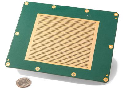
28 GHz antenna for cellular base station
Erfahren Sie, wie Ansys Ihnen helfen kann
Erfahren Sie, wie Ansys Ihnen helfen kann
Contact Us
Kontakt