
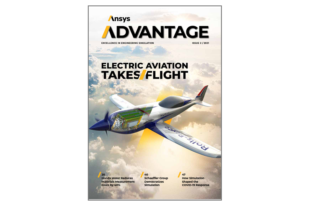
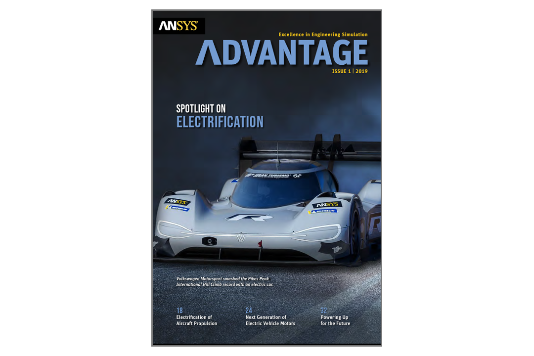
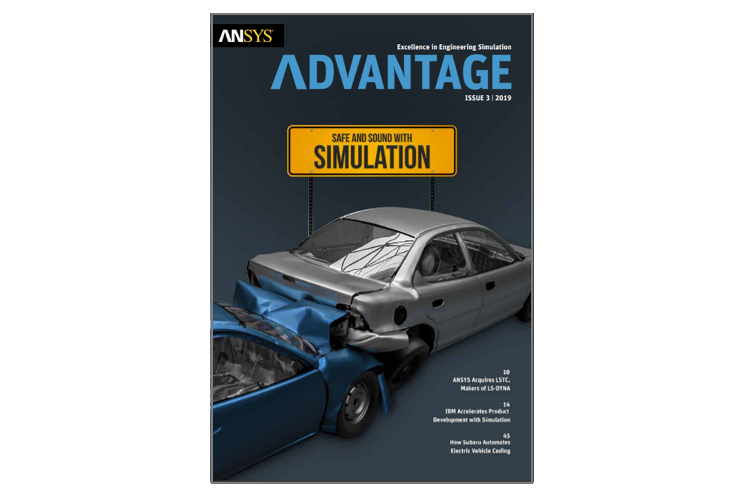
Ansys Advantage Magazine
Discover Excellence in Engineering Simulation
Each issue of Ansys Advantage showcases customers’ stories and important trends across a variety of industries. Learn how engineering simulation is accelerating product development, adding value and reducing costs.
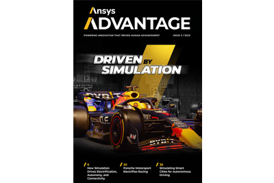
Automotive and Transportation: Driven by Simulation
"For decades, automakers have used simulation to cut costs and time and improve quality in applications such as aerodynamics, durability, crashworthiness, and combustion. Today, the need to use simulation has grown exponentially to address all facets of vehicle design as the automobile becomes more complex."
— Judy Curran, Senior Chief Technology Officer, Automotive and Transportation, Ansys
Learn why OEMs and suppliers partner with Ansys to deliver the highest level of competitive advantage and proven return on investment.
In This Issue:
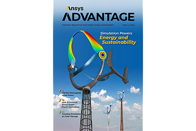
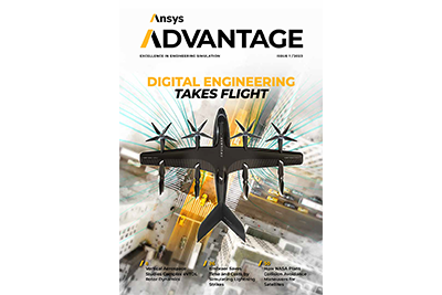
Issue Archives

See What Ansys Can Do For You
See What Ansys Can Do For You
Contact Us
Contact us today