
ANSYS BLOG
June 9, 2022
Ansys EMA3D Cable vs. EMA3D Charge: General Electronics and Automotive Applications
Electronic device design requires qualification of electromagnetic compatibility (EMC) requirements. Traditionally, this has meant development of prototypes followed by testing in dedicated test chambers. Product design cycles are faster than before, putting pressure on the number of prototype and redesign cycles and limiting the time for lengthy test campaigns. EMC adds a major cost and schedule impact to the development of new products.
In the automotive industry, there have been major changes to design practices due to electrification and autonomy. Electrification of powertrains means there are new sources of interference, and vehicle autonomy means that there are more electronic systems deemed “safety critical” within vehicles. This designation means that any EMC failure that affects a safety function is not allowed by government regulation. Failure of EMC testing has significant consequences, as vehicles cannot be sold until the verification is successful.
Conventional approaches including elaborate design rules, frequent and iterative testing cycles, comprehensive verification methodologies, and other standard practices are increasingly ineffective, depending on “after-the-fact” problems manifesting themselves to provide impetus for enhancing conventional development frameworks — in other words, a “school of hard knocks” learning cycle that is painful and expensive in both time and money. These techniques are also inherently reactive in nature.
A more time- and cost-effective avenue is to confront the sources of these problems at the circuit and EM wave level in advance by capturing these electromagnetic phenomena directly in all their complexity. Two of the newest tools from Ansys electronics for modeling and simulating these aspects of electromagnetism are Ansys EMA3D Cable and Ansys EMA3D Charge.
Both tools use some of the same numerical methods to capture EM anomalies; namely, a differential form of Maxwell’s equations solved using the finite difference time domain (FDTD) numerical method. The advantages of this computational basis include speed and scalability. However, the tools are applied to different phenomena.
EMA3D Cable is used to model and simulate electronics enclosures, cables, and transmission lines to capture the coupling effects from these components that induce electromagnetic interference (EMI). An example of this is provided below, using an HDMI cable as the source of the problem and a nearby small PCB as a “victim” of EMI produced by the radiating cable.
Geometry for an HDMI connector, cable, and pins, as well as a nearby printed circuit board (PCB). The simulation is meant to analyze the coupling from the HDMI pins to a net on the PCB.
EMA3D Cable captures a model of this system using a cross section of the HDMI cable and a mesh for the printed circuit board (PCB), its enclosure, and the associated connector. The meshing is fast but also enables the capture of finer features such as gaps, seams, and cable shielding.

Ansys EMA3D Cable mesh of the PCB and HDMI connector. The EMA3D mesh is fast and forgiving for geometry from mechanical computer-aided design (CAD).
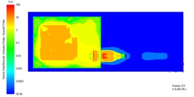
Simulation results for the coupling of the HDMI pins to the nearby PCB. The electric field is visualized on a slice through the problem geometry.
The ability to properly simulate EMI lends EMA3D Cable to the associated task of ensuring electromagnetic compatibility/compliance (EMC) for a system design — a particularly useful capability for automotive applications. The scalability of EMA3D Cable is particularly evident in such an application, permitting modeling of a full vehicle while also capturing cables and their shielding along with seams and gaps at scale. The workflow with computer-aided design (CAD) and import of cables from database software of EMA3D Cable also facilitates the quick development of the model. The hybrid simulation technique is time-efficient. Together, these effects reduce a months-long project to an effort of a few hours.
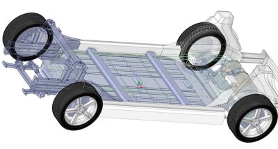
Electric vehicle chassis with battery, cables, motor, inverter, and DC/DC converter.
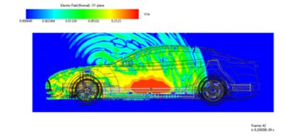
Radiated emissions from power flowing on the vehicle cables.
Electrostatic discharge (ESD) is something familiar to everyone who has felt a shock after walking across the carpet and touching a doorknob. Because ESD can lead to electronic device failure, it is a major design and verification challenge for designers of vehicles and electronics. Previously, modeling ESD arcs in air (non-contact ESD) was considered impossible. EMA3D Charge was developed specifically to make modeling arcs in air easy for users.
For ESD simulations in electronics applications, EMA3D Charge can account for the effects of ambient pressure and humidity and solves nonlinear air conductivity effects in the time domain. Positive and negative particle densities are captured in both time and space. It is a true multiphysics simulation, as it accounts for both fluid dynamics and electromagnetic forces on charge carriers.
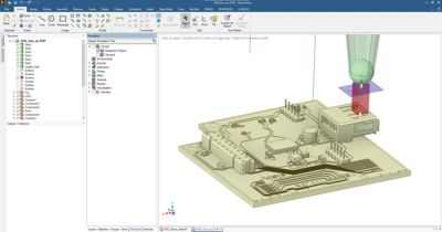
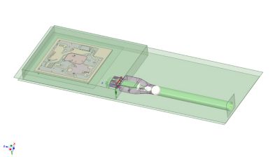
Geometry of an electrostatic discharge (ESD) simulation of an electronic device.
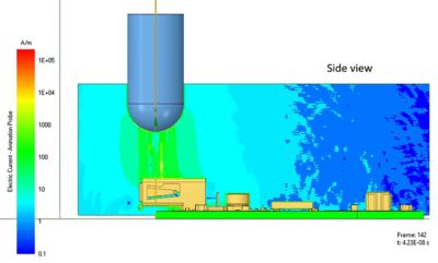
Simulation of the ESD event, which induces voltages in the nearby PCB nets.
The applications for EMA3D Charge in automotive systems are many — from ESD to primary and secondary voltage arcing across the entire vehicle to high voltage-induced component breakdowns. The following images describe a secondary arcing process. ESD is applied to the car handle. This creates a second discharge from the interconnecting cable far away from the door handle. Such secondary effects would be challenging to diagnose and analyze without EMA3D Charge.
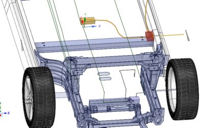
Geometry for a vehicle to analyze a secondary discharge from an ESD event to the door handle. The door handle is electrically in contact with a cable shield near the chassis at a different location in the vehicle. The red box represents a region of air that is allowed to be nonlinear.
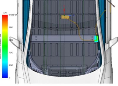
Simulation of the secondary arc. The ESD event is applied at the door handle. There is a secondary arc between the cable shield and the vehicle chassis at a secondary location.
The above is only a light overview of some of the applications where EMA3D Cable and EMA3D Charge can be used, scaling from microelectronics up to system-level end products. A much more in-depth discussion is available in a series of webinars developed by Ansys and EMA covering applications in aerospace and defense, electronics and automotive, and high voltage (HV) and heavy industry designs. You can register for all three webinars here.
For questions and support from EMA, click here.
당신을 위한 Ansys 솔루션을 알아보십시오.
당신을 위한 Ansys 솔루션을 알아보십시오.
Contact Us
문의하기