

ANSYS BLOG
June 29, 2023
What is a Radio Frequency Integrated Circuit (RFIC)?
From cell phones and wireless internet access to radar and navigation systems, the world is becoming more connected using radio frequency (RF) transmissions. Since the technology continues to improve, radio frequency integrated circuits (RFICs) have become complex chips both by themselves and integrated into very large system-on-chip (SoC) solutions. An RFIC is designed to operate at high frequencies, typically in the range of several hundred MHz to several GHz.
The objective of a radio circuit design is to transmit and receive signals between the source and destination with acceptable quality and without incurring a high cost. This can be achieved by designing a circuit using proven design methods. An RFIC typically consists of amplifiers, filters, mixers, oscillators, and modulators/demodulators onto a single chip.
The RF circuit design is a discrete technology that uses both low-frequency analog design techniques and methods used in the design of microwave circuits. The key difference between microwave design and low-frequency analog design lies in the significance of transmission line principles. Microwave design heavily relies on transmission line concepts, whereas low-frequency analog design does not. As a result, the selection of impedance levels and the description of signal size, noise, and distortion are affected.
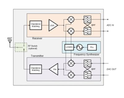
A typical radio frequency (RF) circuit block diagram
The major components of an RFIC design are:
Antenna: used to transmit and receive radio frequency signals.
Filter: restricts the signals in a specific frequency band. It could be a bandpass filter (BPF) that allows a specific frequency range to go through, a lowpass filter (LPF) that allows frequencies below a specific level to go through, or a high-pass filter (HPF) that allows frequencies above a specific level to go through.
Impedance matching: matches the source and load impedances to minimize signal reflection or maximize power transfer.
Low-noise amplifier (LNA): amplifies the weak signals and filters the noise response, as the received signal isn’t strong enough to pass directly through the mixer.
Modulator: used for signal modulation. It encodes the signal in a certain way to meet communication channel requirements. It serves as an "up-converter" in a transmitter, in which it combines a low-frequency analog signal with the local oscillator signal to generate an RF signal.
Demodulator: decodes the signal on the receiver side. It extracts the original information-carrying signal from the modulated carrier wave.
Power amplifier: used to amplify the output of the mixer to a higher power for transmission. The range of coverage increases with the efficiency of transmission.
RF switch: routes high-frequency signals through transmission paths.
Use Cases and Advantages of RFICs
- Wireless communication and connectivity: RFICs are widely used for wireless communication in mobile phones, Internet of Things (IoT) devices, home appliances, and more. RFIC-enabled devices have become an integral part of day-to-day life. Compact integration, power management, and high-speed data transfer are some of its biggest advantages.
- Automotive radar systems: RFICs are used in automotive radar systems for applications like collision avoidance, adaptive cruise control, and parking assistance. Due to its compact form factor, it can be easily mounted in vehicles to provide enhanced safety.
- Wireless sensor networks: RFICs are utilized in wireless sensor networks for applications like environmental monitoring, smart agriculture, and industrial automation. Wireless connectivity between sensor nodes eliminates extensive cabling and infrastructure. Using RFIC-based applications provides flexibility and scalability, since it’s easy to expand or reconfigure RFIC-based networks.
- Satellite communication: RFICs are used in satellite communication systems for tasks such as signal amplification, frequency conversion, and modulation. Wide coverage, high data transfer rates, and efficient signal processing are some of the many benefits.
Design and Verification of Modern RFICs
For decades, analog/mixed-signal design (AMS) was considered an art, and RFIC designers had their own manual techniques that would take them through the schematic and layout phases to physical verification and circuit simulation. However, this would be costly in both project time and budget.
These traditional methods of RF circuit design and verification are inefficient to meet modern RFIC design standards. As designers try to converge analog, digital, and RF into a large SoC — and as the operating frequency continues to increase — it’s difficult to design RF integrated circuits using pre-characterized device libraries or other legacy methodologies. Moreover, electromagnetic interaction at high frequencies leads to parasitic effects such as signal reflections, crosstalk, and electromagnetic interference (EMI), which degrades circuit performance and should be taken into account as early as possible in the design cycle.
A modern RFIC development flow must shorten the turnaround time (TAT) for each design iteration while still achieving the best possible circuit performance. Therefore, design and simulation go hand in hand in an iterative process. A design is tweaked multiple times according to the output of the simulation. It is a long process, and designers sometimes compromise on the circuit performance to deliver according to very aggressive project schedules. In order to achieve performance with no compromises, RFIC designers need advanced electronic design automation (EDA) tools and excellent simulation capabilities with a specific focus on IC design.
The seamless integration of EDA tools — specifically schematic and layout tools — with silicon-optimized simulation software is key for a successful RFIC design. This hyperconvergence of tools provides fast and accurate modeling of circuits from the early schematic phase until the mature layout phase with silicon-dedicated electromagnetic solvers, as well as built-in checks for dynamic voltage drop, electromigration, and other issues. Ansys collaborated with Synopsys to provide cohesive solutions that meet the needs of modern RFIC designers and guarantee reliability and robustness.
The Ansys silicon-optimized electromagnetic simulation workflow starts in the early phases of the design cycle. With Ansys VeloceRF, you can achieve fast and accurate device synthesis and modeling. To make informed decisions during the floorplanning phase, RFIC designers use Ansys RaptorX, an electromagnetic solver dedicated to on-chip designs and workflows. RaptorX can model all the passive elements and routing of a layout, then co-analyze multiple blocks or the coupling between the die and the package. RFIC designers can hand the IC databases over to Ansys HFSS for system-level simulation through the Ansys RaptorH interface, in which they can run full die, package, and PCB electromagnetic simulation. For the signoff phase, Ansys Exalto enhances plain RC results with electromagnetic models for any parts of the RF circuit that are electromagnetically critical. The electromagnetic models are automatically back-annotated in the RC testbench to allow for fast post-layout simulation with electromagnetic confidence.
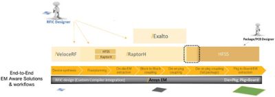
The Ansys electromagnetic-aware workflow for RFICs and high-speed SoCs
This comprehensive solution by Ansys for designing RFICs delivers highly reliable and robust solution, higher yield, and reduced turnaround time.
VeloceRF, RaptorX, RaptorH and Exalto are the industry-leading electromagnetic solutions that can help designers reduce the design cycle time by several orders of magnitude and drastically improve the performance of their RFICs.
The demand for faster and more reliable wireless connectivity such as 5G, which requires more complex and sophisticated RFICs, is driving the development of new RF technologies. To address these challenges, designers can use advanced design methods, comprehensive simulation tools, and optimized algorithms to streamline the design process and reduce time to market.
The collaborative approach to developing RFIC design and verification enables designers to deliver high-quality, reliable ICs. Designers can leverage VeloceRF, RaptorX, RaptorH, and Exalto solutions for easy integration with their EDA design tools, improved accuracy, and reduced time to market.
Learn more about the fundamentals of the Ansys electromagnetic methodology for RF circuits in the webinar “Foundations of Silicon-optimized Electromagnetic Methodology for RFICs.”
Erfahren Sie, wie Ansys Ihnen helfen kann
Erfahren Sie, wie Ansys Ihnen helfen kann
Contact Us
Kontakt